Quantcast
Channel: ElgensRepairs
Viewing all 33 articles
Browse latest View live

Modding a TEAC FD-235 C291-U5 FDD for Amiga use

$
0
0
The floppy drive in my Amiga A600HD had died, and as I'm going a bit miggy-crazy atm I decided to try modding a PC-floppy drive. An old TEAC-drive (model: FD-235 C291-U5) was kindly donated to me by the hardware-guy at work };-P

I did a bit of googling and found that when modding a PC floppy drive for Amiga use, there are 3 things to be done:

  1. Change the device id from DS1 to DS0
  2. Route DiscChangeSignal to pin 2
  3. Route Ready signal to pin 34

Here is first a picture of the unmodded controller PCB


For 1):
Locate the 3 solderpads marked DS0 and DS1 (marked with red box in the last pic below). Desolder the 0Ohm SMD resistor from DS1, turn it 90deg and solder it at DS0 instead.

For 2):
Now, for PC use, the DiscChange signal sits on pin 34, but miggy needs it on pin 2, so we need to reroute it. If you follow the trace from pin 34, you'll see that it ends at pin 1 on the square shaped IC. So solder a wire from pin 1 on the IC to pin 2 on the connector; I used the lower solderpad of S4 (marked with 2 blue boxes in the last pic below) instead.

For 3):
As the last thing, we need the Ready signal at pin 34. As this pin is currently connected to DiscChange, we need to cut the trace. I've cut it at the pink circle in the pic below, but any place will do.
And now comes the only tricky part of this mod. As the PC floppy pinout doesn't have the Ready signal, we must try to locate it ourselfs.
Now it's a known fact, that the DiscVerify in X-Copy, only works, if the Ready signal is present. So I soldered a long wire to pin 34 (the pic below) and then tried running verify, with the other end pressed against the different pads marked with S<number>. When connected to the left pad of S6 (the yellow box in the last pic below), the verify ran. So soldered the wire on there, and tried some games, that I know needs the Ready signal; and they ran too.


So routed the wires a bit nicer, and the mod was a succes.
(Please disregard the wire marked with a pink box. It's just there because i suck at SMD soldering and managed to rip a solderpad including some of the trace off };-S)


A final word:
Now there IS a risk, that I haven't found the right Ready signal; I'm fully aware of this; and should you do this mod, you should too.
But I've used this drive for 2 weeks now, and it works fine. };-P

Homemade RGB-Scart Adaptor for Amiga

$
0
0
As I am working a lot with my Amiga A600HD at the moment, I decided that it was time to get a decent display picture instead of the build-in composite output. The absolute clearest signal you can pull out of a stock miggy, is analog RGB. That is present at the video port, a 23 pin 2-row D-Sub connector. Unfortunally 23 pin D-Sub is very hard to find, so as I own 2 A520 Mod composite/RF-modulators, I decided to gut one of them; then the box also matches the Amiga design perfectly };-P
Now I did have a SCART plug in the pile,


but it had to have the "wings" shortend a bit in order to fit on the back of case; time for Dremel };-P


Next I cut a hole on the back of the case and superglued 2 of the plastic bits on the inside of the box. That way the SCART plug can be slided into place.


And here the plug is fitted...


...and here a glance from the outside.


I then desoldered the D-Sub plug from the circuit board, and mounted it with the screws inside the case again. I had to place a little piece of veroboard under plug, in order to make it fit. Next it was time to draw the wires, and I used this guide for it; ofcause taking care to use the corresponding out-pins on the SCART-plug instead of in-pins, as the guide is for using a male-SCART-plug.


As the video-port on the miggy doesn't provide sound, that is going to be drawn from the two RCA-plugs on the back of it and fed into the SCART-plug. In the pile I found a metalrail fittet with 3 RCA-plugs, yellow, read and white (might be from a scrapped VCR). The pitch of the plugs more or less fittet the 2 holes in the case. Twisted the yellow plug off with a set of pliers, and bended the spare piece of metal around a nearby plastic spike, used for keeping the case from falling apart.


I then superglued 3 small pieces of veroboard inside the case; the topmost has a bit of distance to the side of he case. That way the metal rail rests on the two bigger pieces and is kept in place by the smaller one.


On picture number 3 from the top, you can see, that I've superglued a screw on the other half of the case, to keep the rail in place from the other side as well. Soldered the 3 wires, and was done.


And now: (drum roll!) The Big Test };-P


These pictures are with the build-in composite output (for comparison):


And now with the new adaptor:


I'm pretty satisfied with the result, both the picture, and how the adaptor looks };-P

Amiga A600 quick keyboard fix

$
0
0
Since I've started working intensively on repairing, pimping, upgrading, etc. my Amiga A600HD, the keyboard has been acting up more and more. In the begining it migth fail self test every 10th boot or so (blinking CAPS LOCK and unresponsive), but slowly the frequency of fails rose, and here the other day it went totally crazy. It passed the self test alright, but most of the grey keys were unresponsive; including ENTER };-S

Ok, as opposed to the keyboard on A500, the one on A600 only consists of one big membrane with two contact points for each key. When a key is pressed, the contact points are shorted. Each key is an entry in a big matrix, and no logic is performed in the keyboard itself. The membrane continues into a flat cable with some sort of conducting compound at the end. The end then goes into a special flat-type molex-socket on the motherboard.


In order to be able to remove the cable from the motherboard, you must lift the upper part of the socket, as it works like a lock securing the cable from falling out.


Failing to remember to lift the lock before removing the cable, results in some of the conducting compound at the end, is beeing scraped off.


The reason for my keyboard malfunction is that I'm lazy };-S Often when I mess around inside miggy, I just place the upper part of the case vertically supported against something...WITHOUT disconnecting the keyboard cable. Often I accidently give the upper case a little push, and it falls on the floor, ripping the cable out of the locked socket.

The length of the piece of cable having the compound applied, is a bit longer than the socket (to be on the safe side I guess). So by cutting a little piece of the end with a normal pair of siccors, you get a fresh conducting piece to put into the socket.


Also I added a piece of normal transparent tape on the other side of the cable end, to make it sligthly thicker. That way the conducting compound is pressed harder against the contacts in the socket.


I fitted the cable in the socket again, and presto! Now it works flawlessly };-P

Homemade 1MB Chip RAM Expansion for Amiga A600

$
0
0
As regular readers might have noticed, I've in the process of pimping my Amiga A600HD at the moment. And now it's time to add some more Chip RAM. On Amiga Chip RAM aka Graphics RAM is the memory shared between the CPU and all the custom chips; hence the name "Chip RAM" };-P. A600HD is born with 1MB of Chip RAM installed, and back in the days that was a lot (twice as much as A500!!! };-O). However now-a-days, if you want to run games directly from the harddrive using WHDLoad, it's a little bit on the small side. The 68000 CPU can address up to 2MB, so it would be nice to add an extra 1MB to the pool };-P Now there are some commercial expansion cards that does that; the most popular atm being the A604 Memory Expansion. However it is imo a little expensive and also I really enjoy doing stuff like this myself.
So I started googling for DIY-projects expanding the amount of Chip RAM and quickly found this wonderful hack (now known as "The-A600-Piggyback-Hack") by Zetr0 in a sticky thread over at AmiBay; he piggybacks a DRAM IC on top of each of the 2 already fitted in the miggy. That in turn lead me to this blogpost by Victor Trucco (I ran it through google translate, as I can't read Brazilian Portuguese) via a link in the thread; he piggybacks 2 DRAMS on top of 1 of the already fitted DRAMs.
Now I had some great ideas to work from, however I wanted a solution that was easy to remove again, and also I wanted to give the project my own personal flavour };-P After reading the thread at AmiBay and inspecting the schematics for the A600, it was obvious that all the address-, data-, and control-signals needed for the extra Chip RAM are present at the trapdoor connector. So my plan was, to attach the 2 extra DRAM-Chips piggybacked together there. After doing some crude measuring, I found that the pitch between the pins in the trapdoor connector is the same as in a socket for PCI-card to fit in a PC.
I didn't have neither DRAM-chips nor PCI-sockets, so I went hunting on evilBay and quickly found a guy offering a lot of 10 Toshiba TC514260DJ-60 SOJ chips for a price of only $15.33 incl. shipping to Denmark. Next I found a lot of 5 PCI slots at a price of $7.41 incl. shipping.
I waited and waited, but finally both lots arrived in the mailbox };-P Now I had all the stuff needed; for wires I was going to use rainbow ribbon cable (having the same pitch as the pins on the DRAMs), as I just love how is looks like candy };-P


First I checked if my measures had been correct (I had just tried to match up the pins using an old PCI card). Luckily, it is a perfect match };-P


The first thing to do was to prepare for the "marriage" of the two DRAM ICs. Being of SOJ type, they have their pins bend underneath themself, kind'a like a dead spider. So the one to go on top, had to have the pins straightened. First you lift the pins carefully with a Stanley knife.


Then use a set of pliers to make each pin straight. Here's the final result.


One pin is bend upwards. That is the RAS (Row Access Strope); the only control-signal that is not the same for the two ICs.
Next our happy couple are pressed together and "married" (do I hear wedding bells? };-P).


After that's done it's time to cut them rainbow ribbons.


The longer blue wire is for RAS on the upper IC. Luckily the IC-pin just beside the the RAS is NC (non connected), so no harm is done using that for the upper ICs RAS.
First the pins 21-40 are soldered.


Next the pins 1-20.


Now all the wires must be soldered to the PCI socket


using these mappings:

(the clever student will notice that the headers of the 2 first columns of the last mapping have been switched around)
And now for the big test (first I tested without the caps shown in the picture)


Now WorkBench found the new extra 1MB alright.


But when trying to use it, things got bad. The memory tester i use reported many random errors (random meaning not at the same addresses everytime) and when trying to load big games (like Cinemaware-stuff), I got random crashes.
At first I thought that this was a problem related to smoothening and/or decoupling, so I tried adding one 220nF capacitor across each supply to the ICs and one 2.2uF capacitor at each end of the powerrail for the ICs. That only made things worse...so removed the caps again. But now I still had as many errors as when they where still fitted. Grrrr!!!
Decided on giving the whole project a rest for a few days };-S

I made a post in the thread over at AmiBay and Zetr0 replied, that technically the solution looked fine. However he thought that caps might not be the way to go as they might induce more noise into the circuit than they'd remove. He also mentioned, that I might've toasted one or both the DRAMs and proposed that I either tried to test the two ICs individually or started all over with a new set of ICs.
I desoldered the IC couple and tried to divorce them, but it was not possible without destroying them completely. So in the bin they went. I made a new couple just as before and soldered them on the ribbons, but it ended out in one big mess. These ribbons are not meant for soldering in the first place, so the heat from soldering, desolering, and resoldering had made the insulation into one big pile of goo. So desoldered the new couple again.

I now decided on trying to use kynar instead of ribbons. They are much thinner and singlecore, making it much easier to control. However I was sad to give up on the ribbons, as they just look so cool };-(
Following an idea given to me by Phipscube (a dear personal friend and also an AmiBay member), I taped a piece of cardboard to the PCI socket and taped the ICs upside-down on it. I cut a hole in the cardboard for easy access to the lower pins of the socket when soldering. Then I started soldering the kynars one by one.


Again following a good advice from Phipscube, I did the soldering over a couple of nights in order to be fresh in the head...otherwise you end making a mess.
The really nice thing about kynar, is that it is so small and thin. However, the really annoying thing about kynar, is that it is so small and thin. Elgen
The final result looked like this.

(please disregard the fact that the PCI socket is now shorter that before; that's because this pic is actually taken a bit later in the process, 'cause I got too eager and forgot to photo-document };-P)
Once again time for a test in Miss Miggy, but (MOAN!) I still had the frakkin' random errors! };-S
Tried to add caps, and again it just made things worse!!!
Now I was so close to giving up and trash the whole gorram project. However during the day, I came to think of good ol' Faraday and his cage. Hmmm, maby the instability was caused by electromagnetic radiation from either the near-by circuits, or maby just general radio-wave-noise. So after having tucked the kids in that night, I first wrapped the construction in paper to insulate


and then in tin foil (yup, the same kind I use for my kiddies school lunch };-P). I attached it in the trapdoor and connected the tin foil to ground. Aaaaand....


Heureka! The random errors had gone away! };-P
"Dad, did you put chips in my lunch pack for dessert?""Sure did son, but not the potato kind };-P"
Now I had something that worked; it was time to make it look good too };-P
First I gently lifted the ICs from the cardboard using a Stanley knife. Then replaced the cardboard with a smaller piece that didn't have the hole in it.
Next I cut the PCI socket down to the same size as the connector in the trapdoor using Mr. Dremel and a small file. I then cut the end of the piece that I'd cut off, and superglued it to the end of the now smaller socket.


And now for a nicer Faraday cage.
Ever since I started doing electronic projects as a kid, I've always had this thing about having some tins in different sizes (from canned good) on my work bench. They often come in quite handy; as tabletop trashbins (for things that you might/might not need again later in the project); for small things (screws etc.) when you dismantle devices; for very hot solder when you clean the filter in you desoldering station; find more uses yourself };-P
Bottom line, I had this little fellow stading on the table that day.


I scraped a little bit in the paint and found that it was conductive and normal solder for electronics would bite on it. So I cut off both ends and cut the tube open using my Dremel.


(But perhaps I should've used a heavy duty disc instead of a normal one; the one on the right is a brand new disc };-P)


Next I cut out one big piece (top and bottom of the cage) and 2 smaller ones (the sides) using an old pair of scissors. I then bend the large piece and soldered the sides on leaving a hole for the socket.


As the last thing I soldered a wire from GND on the socket to the cage in order to ground it, and here it is in all it's glory:


And here fitted in Miss Miggy (and it still works };-P)


I wish to thank Zetr0 (AmiBay) for inspiration and good advice, Victor Trucco (blogger) for inspiration, and Phispcube aka Les (AmiBay and dear friend) for good advice and cheer-ups through many many txts often very late at nite };-P


Finding, repairing, and enhancing a Commodore C1901

$
0
0
My friends often tell my that I'm often lucky to stumble upon cool stuff that other people have trashed. And, hmmm, well maby I actually am };-P.

This day I was out walking with my daugther (age 8years) and I had my youngest son (age 1½years) in the pram. Suddenly in the corner of my eye I saw the well known Commodore C= logo at the other side of the street. I rushed to see what it was; a lot with a C128, C1901 monitor, and some smaller stuff. As it was raining a bit, I didn't get a close look at it, just stuffed the things under the pram and took the monitor in hand. Steering the pram with one hand, holding the monitor in the other, I began the trip home.
When I got home, I had a closer look at my loot.

A C128
with PSU, joystick,
1571 drive, datasette,
and last but not least: A Commodore 1901 monitor
But, as you've properly noticed from the photos, the people who'd thrown these goodies away, had been so 'kind' as to cut all the wires they could find before trashing the lot };-S

Well first thing to do, was to let the whole lot rest in my nice warm basement for a couple of weeks in order to dry it up. After that, I decided on having a closer look at the monitor to see if it was alive. As the power cord had been cut by the former owner, I fitted a power plug I had from and old defect ATX-PSU. The hole in back casing was already prepared; it was only a matter of cutting the plastic bit out with a Stanley knife.


I connected a power cord and pushed the switch. I heard the well-known sound of a degaussing circuit and the high frequent noise from the tube powering up };-P But then there was a loud POOOF, then a loud hissing noise, and then white smelly smoke began to emerge from the insides of the monitor. ARGH! Quickly I pulled the plug, and the smoke stopped emerging. PHEW! I did this testing in the evening in my workshop in the basement; and my workshop happens to be just next door to our bedroom. I was NOT the popular husband that night, as the smoke was extremely smelly; a bit like rotten fish mixed with the smell of old fart };-S

Hmmm, the next day I had a closer look inside the monitor to see if I could find the source of the white smoke. But nothing was obvious... I had to try and apply power again! To avoid getting a divorce attorney on my back, I did the testing outside this time.


...but to my suprise, no smoking and no hissing from the monitor?! The bright light outside did however help me get a good look inside. And near the front of the monitor, I found this little felow.


By googling a bit, I found out, that this is what is known as a so called safety capacitor. I don't really know what it is there fore, but it was obviously toasted. So I desoldered the poor thing.


In the defective ATX-PSU mentioned earlier, I found this little guy with the same specs, as the one I've just removed from the monitor.


So onto the chassis PCB it went.


Now there was no hissing or smoking anymore };-P Time to see if the monitor actually worked. I googled that the inputs was digital RGB (used by the C128) and composite. So I hooked up my Amiga A600 through it's built-in composite module and got this


Hmmm, no colours?! This looked an awefull lot like a Commodore S-Video signal missing it's chroma input. Did a bit more googling, and found that this monitor model came in different flavours: With composite input, S-Video or both, but it seems like the chassis is the same on all these; you can just add the missing inputs. However my googling also led me to a blog runned by a guy calling himself JetSetSkippy. He had this awesome post, where he amongst other things, retrofits a C1901 with a SCART plug enabling it to be used with true analog RGB-input (15kHz) };-P This was almost too good to be true, so I found a SCART plug in the pile and started right away.


As Skippy also explains, this chassis is already prepared for a SCART plug (notice the 2 rows of holes in the PCB just below the D-Sub in the pic). But the crazy thing is, that the designers must have gotten something wrong; cause the holes are reversed so you can't just solder in a standard 90 degree angled SCART plug. Maby that is also why this monitor ended up not being shipped with a SCART plug?! Therefore I (like Skippy) soldered wires on all the pins of the plug and began the cumbersome task of soldering them onto the chassis.


Phew! All the wires had to fit in a really tight spot, but finally I pulled it through (look under the black ribbon cable).


The plug was then attached to the metal frame in the hole already there...


...and the plastic casing was cut.


And now for a test };-P I first attached the A600 via my homemade RGB-Scart adaptor and the result was fantastic.


Next I tried an arcade PCB (attached via my homemade SuperGun) with equally fabulous results.

(disregard the moving sprites };-P)
All in all, I consider this a great success! And should any of you guys out there have an old C1901 in the attic, I strongly encourage you to fit it with a SCART plug. It gives a very clear and crips picture, and the chassis is all analog with lots of knops, dials, and switches to make adjustments with. So far it has been able to sync with everything I have feed it, so it's going to be my main test monitor when I do repairs from now on.

What an awesome finding on a rainy day };-P

Retrofitting an USB-port on a Fluke9010A

$
0
0
Late November this year, I managed to snap up a dead-cheap Fluke9010A Microsystem Troubleshooter from evilBay. I owe tlosm aka Luigi from Amibay.com much gratitude for agreeing to act as middleman, as the Italian seller would not ship outside Italy except for a very unreasonable price. I ended up paying 65EURO all-in-all (half of what I would have paid if dealing directly with the seller) };-P

What I didn't know, was that a pleasant surprise was awaiting me upon receiving the machine: It was equipped with both the RS232- and the 006-option! };-P

After some visual inspection, I found that it had a few scratches, was missing a couple of screws and the tape drive, and was pretty dirty, but it powered up nicely and passed the self-test.


So I decided to clean it a bit.


and ended up with a machine that looked pretty decent (and still passed the self-test).


Now in order to start playing with this wonderful machine, I would need some interface pods. But that can take some time to find, so in the meantime, I would try to use the RS232-option to hook up it up to a PC using FIDE. Now I do have an old laptop with a COM-port, but would much rather like to use my lovely Lenovo that is my primary PC, but only has a couple of USB-ports. So I went to evilBay and ordered a cheap little USB-to-RS232 Adaptor. After a week or two it arrived.


In order to use it with the Fluke, I would need a cable too...or would I? Hmmm, the adaptor was easily disassembled by pressing gently on the USB-plug revealing a tiny PCB with both plugs soldered directly onto it.


My plan was to built this into the Fluke and add a USB Type-B plug on the backplate here.


So I started by desoldering the D-Sub from the adaptor.


Next it had to be hooked up to the Flukes RS232 port. The port is attached to the PCB by a 6-way molex connector (only 5 pins in use).


If you press very gently (but firmly) into the holes on the side of the molex plug with a small screwdriver, you are able to pull out that connector. My plan was to "piggybag" these 5 connectors with wires.


Next I hooked up the adaptor according to this diagram. I plugged it into the PC, fired up FIDE, prepared the Fluke and tried to send a sample program. Nothing at all happened on the Fluke! };-S Hmmm, went back and had a read in the Fluke manual and discovered that one should use a null-modem cable and not a strait-through. So changed the wiring according to this diagram instead. Now at least something displayed on the Fluke: Sometimes I got "PARITY ERROR" and sometimes "FRAME ERROR". Tried a bunch of different combinations with speed, parity, number of databits, and start- and stopbits. Still same-same. I decided to let the whole thing rest for the night, as I was also i bit tired.

Next day, fresh in my mind! I discovered a little white marking on the turnwheel to set the RS232 speed on the back of the Fluke (see pic higher above). Until now I had though that the slot you put the screwdriver in was the indicator of the position, but having a closer look at the white marking, I could see the shape of a small arrow underneath it. AHAAAA!!! He cried out loud! I now put the turnwheel into position 7 according to the arrow and presto... I was able to upload my sample program


and execute it


Fantastic! So it was actually possible to communicate with the Fluke using FIDE on Win7 (32bit) and a cheap USB-to-RS232 adaptor };-P Now I could have just stopped there with the USB-wire coming out of the tape-drive hole; but I wanted it to look a bit nicer than that.

I dug up this little PCB from the pile (have no idea what it's for) and a piece of shielding metal (as solder bites on it)


Desoldered the USB Type-B plug and made 2 small wings from the metal piece using the Dremel. I then soldered the wings onto the sides of the plug.


Next I found a nice place for the plug,


made the hole using Dremel and some small files, drilled 2 holes and attached the plugs using small nuts and bolts.


Here is a picture with the USB cable plugged in


and here a look inside the Fluke


All in all I'm pretty satisfied with the result, and I don't have any fuss with messing around with adaptors and null-modem cables when working with the Fluke.

Last but certainly not least, I have to send a big round of thanks to Andy aka Andreas who is running andys arcade for kindly selling me 3 interface pods here just before Christmas. It was Z80, 6502, and 68000 (the 68000 was even from his private collection). They all passes self-test, but besides that, I haven't had time to play with them with all this Christmas going on.


I Wish You All A Very Merry Christmas And A Happy New Year };-P

Sega Wonder Boy III Monster Lair Bootleg Repair Log

$
0
0
This board actually started out as an unknown. I traded an original working 1942 (as I don't like the game, and didn't play it) for 4 defective boards and some cash with a fellow collector from spille-maskiner.dk. Three of them was: Miss Pacman, 1942 and Psychic5 (all bootlegs), but he was unable to identify the last one (clearly also a bootleg). So I read 3 of the PROMs and ran MAMEs romident on them


SWEET! I haven't got this game, and ever since beeing a little boy, I've loved this game; mainly because it's 2-player but also because of the super-cute graphics and the nice mix of platform and shmup. Now let's see if we can get it up'n'runnin'.
After having a quick look at the edge connector, I took a chance and hooked the board up to my test rig / SuperGun via my Sega System16 adaptor, as the original board is System16. I got these screens


Cool, System16 was obviously the correct pin-out. Tried touching different parts and ICs on the board and looked for changes in the graphis, and when pressing down on the daugther board on the primary PCB


I got this


Lovely...this seemed very promising indeed };-P This might turn out to be an easy fix...
I cut the power, and took off the daugther board


Hmmm, 6 standard 20pins DIL-sockects to grap hold of the reletively long pins on the daugther board; not the most durable (or smart) solution ever seen };-S Well, had a closer look at the many pins, and they all look healthy. But when turning to the DIP-sockets, I found this


It looked like the daugther board had at some point been forced into the sockets, but with 2 of the pins sligthly bend causing the metal in the coresponding DIP-holes to be deformed. This would surely cause bad contact for the 2 pins, and maby some of the others, as the board migth not be fitted correctly. I didn't have any new sockets, but found a decent looking one on one of my scraps. Removed the damaged socket


and fitted the one from the scrap board


Here I have to mention how much I love my desoldering station. These 2 small desoldering tasks could easily have taken me 1+ hour instead of the 5mins I used };-P ... and with no damage to the socket nor the PCBs.

With the daugther board well fitted again, I powered up the game...and LO AND BEHOLD!


Now the next thing to address was, that until now the game had been dead silent, also when coined up and started! First thing I found, was this loose cap near the amp


The cap itself didn't look like it was knackered, so cleaned the holes and soldered it back in.


But still no sound; not all that surprising, cause after a closer inspection of the System16 pinout, this cap was merely a smoothening cap with no direct connection to the sound output; it just happend to be close by.

Tried running a finger over the pins of the amp while having the volume pot at both extremes, but didn't even get a slight hiss; clearly no signal at all got through to the monitor! I carefully lifted the amp from the PCB in order to find a part number


After A LOT of googling, I finally found some useful info at andysarcade.de; here's a screen dump of the pinout:


So tried hitting the output (pin 5) with the scope


Now that surely looked like sound to me, and the pattern also changed, when coining up, pressing start ect. So the amp seem to work. I then traced the signal through a cap and then straight to SPEAKER- on the edge connector. Hmmm, wait a sec. what about SPEAKER+ then? By using my continuity tester, I found that it was connected directly to GND. Now while this would work flawlessly if the board is connected to a cab with a speaker, it was now clear to me why I didn't get any sound on the monitor. In my homemade SuperGun I feed SPEAKER+ and GND directly into the SCART-plug for mono-sound, so in this case, that would leave me with 2 x GND };-S
A quick criss/cross of the two speaker wires on the System16 adaptor, and I had sound.
Now as I usually play arcade games on my SuperGun and not in the cabs, and as this is not an original but a bootleg, I decided to cross the two lines on the board instead (had it been an original, I'd made a custom adaptor instead). So found a place where they ran close together, cut the traces, and soldered two small pieces of wire on.


The game is now fully functional (also with my SuperGun), and I'm very happy to have it in my collection. However, it would be nicer to have the original, but you rarely see them up for sale...

Capcom 1942 Bootleg Repair Log

$
0
0
I got this board about two weeks ago when I traded an original 1942 for 4 defective bootlegs and some cash. I was told that the game was ok, but had problems with the controller inputs. When I got it, it looked like this


I'm pretty sure that there exsists a very special and particularly gruesome place in Hell for people who solder their adaptor wires directly onto the PCBs connector };-S It is just so cumbersome to remove them again... But after about 30min of hard labour, a good 20cm of solder wig, and a light scrub with rubbing alcohol and toothbrush,


I had a result I was pretty satisfied with.


Now, as this board has a 44pins pinout, it couldn't be Capcom Classic (like the original) for sure, so I grapped a 44 pin edge connector and a JAMMA fingerboard from the pile, and went hunting the net for the pinout. And at mikesarcade.com I found something that looked like it was the right one (notice the 5 consecutive GND-pins in both the pinout over at mike's and on the pic of the component side above). Even though I was about 99% sure it was the correct pinout, I built the adaptor in steps with supply + video, sound, and then controls, with testing in between each step. However after I added the controls, the sound was gone.


Hmmm, checked all the connections again and tried to wiggle the board i bit while it was running. I managed to get sound momentarily. Okay, so my adaptor was fine...the board had just developed a sound issue while I was fiddling with it.
Now on to the controls, that I've been told was screwed. First thing I noticed was, that the game started right after I hit the coin button. Next the plane used up all the rolls, then flew to the top of the screen shooting constantly.


The only control function responding, was left on the joystick. I started with the start button. First I found it at the edge connector, and a continuity tester confirmed, that it was tied low. Luckily I was able to trace it backward using only my naked eye. First thing it met, was this array of pull-ups.


Now the first resistor in the array seemed to pull up fine


But the next couple of them


was tied low.


However after desoldering, the array seemed just fine, when tested with the Ohm-meter


And (not all the surprised) I found that the pins were still tied low on the board.


So the array was going to be soldered back on the board, and I went looking upstream. The next thing the line met, was the 367 just below in the picture above, so out it went


And BINGO, it tested Bad!!! in the Top };-P


So fitted a socket and found a good 367 from a scrap board.


But when I then powered up the board, all I got was this screen of garble. WTF!!! };-S


Tried turning power off and on a couple of times, and even tried putting the old 367 back, but still same-same... Well, back to basics: Did visual inspection of parts and solder side for both PCBs. Reseated all socketed ICs and dumped all ROMs


All seemed correct there as well. Desided to hit the sack and sleep on it, as I was pretty tired.
When I got back to the board the next day, the first thing I noticed was this


Not all the dip switches on SW2 was fully off! I set them all off, and the game booted just like it had done before };-P After I had a look at the dip settings, it was obvious, that switch 1 on SW2 must have been on causing the whole game to freeze. Well lesson learned: If something really stange suddenly happens to your board, check the dips first };-P
Now, on with the REAL repair };-P The start button was now functional, so the game didn't start right upon being coined up anymore. However, the plane still used up all the rolls and flew to the top of the screen when starting the game. So traced the loop button back to a resistor array and a 367 just like with the start button. This time I started by desoldering the 367


and it tested as BAD!!! in the Top. So a socket and a new one from scrap was fitted


Now the game played perfectly, except for the missing sound, that is.
Missing sound can be caused by many things, but I usually start by checking the amp. This can be done by maxing the volume-pot and running your finger over the pins of the amp. If you hear a hissing sound, the amp is not totally dead. Here, there was hissing. As I had just done a Wonder Boy 3 Monster Lair Bootleg, that uses the same amp, I had the pinout right at hand. So poked the input with the scope, and saw a total flatline. Next I found the pinout of the two AY-3-8910 sound chips, and had a look at the 6 outputs (3 each) with the scope; again dead silent. Then started checking the datapins sitting on the bus between the two sound chips and the sound CPU (a Z80, just like the main CPU). AHA! data pin 3 was always low.


I was pretty confident (maby because that had just been the case with the control lines), that whatever was pulling the line low, had to one of the ICs on the data bus. So first I removed the ROM; easy as it was already socketed. Still stuck low! Next I suspected these two 374s


So they was desoldered and sockets fitted. But they checked out fine in the Top and the line was still low.


In the maintime, I had found that the sound circuit is identical to the one on the original. So by inspecting the schematics (page 3) found at jammacade.net, I could see, that the only ICs left on the bus, was the CPU, the RAM, and the 2 sound chips. Now, if the CPU was knackered, it had to be desoldered anyway; if not I could solder in a socket and have a great chance to try out my new toy, The Fluke9010A };-P So desoldered the CPU and fitted a socket instead.


And now....Fluke-time! (Ooooh, exciting!!! };-P)


The Fluke showed just what I'd discovered myself


So the CPU was innocent. Ofcause, I was not able to do any of the other tests until I'd solved the problem with the stuck data line. The only things left on the bus was the RAM and sound chips. However, before desoldering any of them, I desided to visually inspect the circuit lines of the bus just one last time. Then I found this...


This grounded soldering was very close to the stuck line, and when looking through the magnifying glass, I could see that it had taken a little hit at some point. So I gently made a cut with a Stanley knife to separate the soldering from the line...


And when I booted the game, I had sound again, also with the CPU back in place. };-P
But as I had the Fluke powered up, I did the BUS test


Found the RAM-space via the MAME source


and did the two RAM tests (short and long...beware, the long one takes very long time)


Finally I used porchys great little tool Fluke 9010 Sig Calc to calculate the signature for the ROM and do the ROM test


I find that the Fluke is nice and easy to work with, and that it has a lot more potential than what I've done with it here...I'm so very happy with it };-P

Case closed; I think I'll try to trade this board for some other defectives, as I don't like 1942 that much.

Fix It Felix Jr Outfit

$
0
0
I know this hasn't got anything to do with arcade or repairs, but I still the urge to...HEY wait a minute, this actually DOES have a lot to do with both arcade and repair };-P

The whole family was invited to a costume party at my sister in law. However couldn't decide on what to wear. But the day before the party, when I was at the movies with my oldest son to see Wreck It Ralph, it struck me: I'm gonna be Fix It Felix Jr  };-P

So I spend 1½hrs with what I could find in the house and a hotglue gun, and this is the result!

I Can Fix It!

Taito Super QIX Bootleg Repair Log

$
0
0
Now this little bootleg of Taitos Super QIX had graphics issues. All the sprites had stripes through them; the same with some of the letters on the attract screen (maby they are made up of sprites too?!)


I started with the basics. Visual inspection, reseating ROMs...however when putting this 2732 back in place, I just got a solid blue screen


Tried popping out the ROM again. It was then I discovered, that the dumbass that had fitted the socket, had reversed it (notice, that GND and not Vcc goes to the upper right pin of the socket)!


The result was, as I feared, that the ROM was now fried. When trying to read it in the Top2005+, I got a "No chip inserted!" error. Ofcause I had forgotten to dump the ROM before I reinserted it and flipped the switch, so basicly, if I couldn't find the right image somewhere, I was frakked. So I went hunting the net for ROM sets. By googling a bit, I realized that my board was a special bootleg using a MCU with external ROM; the other ones have an MCU with inernal ROM. So the image I was after was called sq07.108. This image exsists in (at least) 3 version floating around the net. Tried burning one of them, but my Top2005+ would not burn 2732's with Vpp=21V. So I tried programming some 2764's with doubled image, and then afterwards moved some pins around to make it fit the 2732 pinout. None of them worked!
I was then so tired of the board, that I sentenced it to the scrap pile!

Months went by with other reps, but everytime I had my hands on the board while going through the pile, I thought of how sad it was to scrap such a nice board. So a couple of weeks ago I pardoned it. It had suffered a little bit durings its stay in the pile; the volume pot had been harvested for a rep (that I gave up on, as the game was TOO damaged, and was a football game). Besides that, it looked just fine.

Now I was pretty sure, that all the ROM sets I'd found wouldn't work, as it was the wrong images for my game. So I sent out a cry for help by posting threads, on different rep forums I usally visit, asking if anyone had a bootleg similar to mine.
Mainwhile I also had the thought, that maby the board (for some reason) would only work with a true 2732, and not a modified 2764. A couple of months earlier I had been so lucky, that an old friend (Jarl) had decided to donate me his old ISA BUS based EPROM programmer that actually IS capable of programming EPROMs with Vpp=21V. So tried one of the three images I had


With this EPROM the board booted up the self test and passed all tests and then went all black screen when the game should start. Now that was certainly a change for the better };-P So erased the EPROM again and tried one of the other images, and BINGO! I was back at square-one with a game that had sprite errors; Totally awesome!

Now sprite errors like these are often caused by bad RAM, so started poking the data pins on the different RAMs on the board. This board uses 4bit DRAM for sprites and backgrounds and they work in pairs to make up a whole byte. I had never encountered a board using DRAM before, so I was not too sure what to look for, as DRAM also has this thing about refresh. However, when poking this little fellow


I saw something that didn't look at all healthy; refresh or not

(0V is in the middle and 5V is 3 squares up)
And when looking at its partner


with this dataline


I was convinced, that something was very wrong with the other DRAM! However, as my Top2005+ only tests SRAM, I had no means of testing it. So I decided on desoldering both ICs in the pair and fit sockets.


By trying diffenrent combinations of inserting 1 or 2 ICs in the different sockets, I was pretty sure, that the one with the fainted text was knackered. I went through he scrap pile, but didn't find any 41464...however I found this old PC mother board with alot of these 41256s


Now while 41464 are 4bit DRAMs, the 41256s are only 1bit...let's try and look at the math: 1 x 4bits = 4bits = 4 x 1bits; AHA! (this is the sound of Elgen getting one of his crazy ideas) Why not try stacking 4 of those 1bit DRAMS? };-P So harvested 4 of them and started preparing them. I found the pinouts here (here is a screen shot from my iPhone)


The 41256 has separate D and Q, so they would have to be connected


Next we stack'em and connect all the address and control pins


Now as seen on the pinsouts above, the placement of the addresspins are not compatible, so I prepared an old socket with solder blobs


and soldered the pins that where in the right place on; then routed the other pins using kynar; the only pins not present on the 41256's was the /OE (output enable), so I just left it unconnected


And now...the big test! };-P (Ooooh, so excited, I almost wet my pants)


AND IT FRAKKING WORKED!!! };-P


Even though it worked, I did order some real 41464's on evilBay, as the MacGyver construction is not very durable };-D But it was great fun trying and it was cool to see that only the one DRAM was dead.

Next problem to address was no sound. So started by refitting the volume pot, but still no sound. The output of the amp


looked fine though


But I traced the signal to the SPEAKER- pin at the edge connector; hmm precisely the same 'problem' as with this board; maby it's time to add a switch on the SuperGun? But I decided to switch the signals onboard this time again


and the sound was now perfect.

Yesterday the real 41464's arrived from the US


and the board still works fine with one of them


Case closed! };-P

Addendum: My cry for help on the different forums payed off! I got a pm from member Belike on Dragon's Lair Fans, that he had an untested bootleg SuperQIX (also with an MCU with external ROM) that he didn't mind parting with for small money. A couple of days ago it arrived. I haven't had time to test it, as the pinout is not JAMMA, but I did desolder and dump the ROM, and it has precisely the same CRC32 as the one from MAME I'm using in my own SuperQIX right now };-P

Capcom Gun Smoke Bootleg Repair Log

$
0
0
All I used for this easy 'rep' was

my flathead screwdriver; actually my favourite tool...really love it <3
my trusty soledering iron
and a bit of common sense
I got this board as a part of the trade for this bootleg 1942 that I'd just recently fixed. I was told that the board booted and coined up, but when pressing start, it would freeze. The pinout (2 x 28) was a bit strange; not like anything I'd seen before (certainly not Capcom Classic)


(the key is at 8 like on Capcom Classic; pin 26, 27, and 28 on parts side is GND, but on solder side it's only 27 and 28). However the game came with a JAMMA adaptor that made it boot, so I just started by using that.

Just as described, that game booted up just fine


and also coined up


But when pressing start I got this screen


for a second or two before the game rebooted (the watchdog jumped up bit the main Z80 in the butt };-P). The same thing also happend when the game ran in attract mode and was to show the in-game sequence.
So I started with the basics: Visual inspection, dumping ROMs and reseating all socketed ICs. During this, I quickly found this area interesting


Somethig didn't look right; ROMs no 3 and 4 facing one way, while 5 was facing the other. When I pulled no 5, it was obvious by looking at the circuit lines, that it had been inserted the wrong way. Often this causes the ROM to get fried, as they are very sensitive to getting polarity reversed. So I turned it around, crossed my fingers, and got this


Even though the screen look garbled, this was the intro sequence for sure, and after that the actual game also ran...SWEET! };-P (no sound though).

I was finish with basics on the main board, so turned to the graphics board. Here I found this


This didn't seem right either. In the first row we have 7, 6, 8, 9 and in the second row 10, 11, 12, 13... Well I'll be damned, if that first row shouldn't read 6, 7, 8, 9 instead. So I tried switching the two


and now had a garble-free intro sequence


The game itself played fine, but the cowboy was only able to shoot forward and left. A quick look at the adaptor, and I saw, that only two buttons were wired on the JAMMA fingerboard. Now I couldn't find that strange pinout anywhere on the net, so I just tried poking a grounded wire at the different unused pins. And on pin 20 on the parts side


I hit the jackpot


So soldered an extra wire (the white'n'red one) on the adaptor


The last thing I needed for this to be perfect, was sound. There was already wires from two pins on the edge connector to SPEAKER + and - on the fingerboard. So from previous repairs, I know that it's smart to try and switch the wires (when working with a SuperGun and not a cab with a speaker) before trying anything else. And because we have an adaptor in play, luckily that's quite easy. And, PRESTO! the sweet sound of gunfire filled the room };-P
The game now plays perfectly, and I ended up with a pinout looking like this

If anyone out there has more info on this pinout, don't hesitate to leave a comment };-P

Capcom Three Wonders Repair Log

$
0
0
This board was sent to me by my dear friend Alf81. When turned on, all you got was a black screen and something that sounded like a burp from the speakers. As this game runs on CPS1 hardware, the thesis was, that it had committed suicide. But what does that actually mean?
Well, by the end of the Golden Age (mid 70's to mid 80's), the arcade manufacturers discovered, that if they made the games so durable that they lasted too long, the arcade owners would not buy new games. They then came up the idea to install a mechanism into the games, that would render them useless after some time. And even unrepairable by 3rd party arcade reppers. This is what is known as a suicide mechanism, but in fact the name is a bit miss leading, as it implies an active action; in fact it's kind of like the opposite:
(EDIT: Womble (RCM, AussieArcade, etc.) pointed out in a comment, that I'm on the wrong track with this theory. As he has far more experience than me, and as his explanation sounds more plausible, I think he's right. You can read it here.)
The principle is almost the same for all flavours. You take a part of the game code (usually vital for the game to run, but early examples also includes only the sound system ie Shinobi) and encrypt it before putting it onto the ROMs. Then you put the decryption key into a small block of RAM hidden inside some custom chip and add a battery on the board to keep the piece of RAM alive even when the game is turned off. At some point, the battery will run out of power, and the RAM will loose the decryption key forever. The game can no longer read it's own game code and is unplayable, and as the decryption key is gone, the game can't be 'fixed' by anyone else but the manufacture (at a high price).

Cosmetically the board seemed to be in good shape.


so right away I had a look at the usual suspect, the battery. On CPS1 systems, the battery as well as the custom chip containing the RAM for the decryption key, is placed on the little sub board called the C-board


So I tried putting a voltmeter on the poor thing and got this


This battery was surely stone dead! So what can you do? Well, when I said before, that suicided games was not fixable by any 3rd party repper, that was not entirely true. Cause here in modern times, ultracool software/hardware hackers (not me) have found ways to pre-decrypt the code so that it will fit on the ROMs. It is then possible to put the custom chip into it's non-decryption mode, and it will be able to read the (now) decrypted ROMs. The game will rise from the dead.
The #1 place to get these pre-decrypted ROM images is at The Dead Battery Society. Here you will also find instructions on how the make the appropriate hardware modifications to your dead game. I this case (CPS1), you have to first remove the battery, as it will not be needed anymore.


Then break the connection on two adjacent grounded pins on the custom chip and set them high instead. I'm not that good at SMD's, but with a little help from liquid flux, I managed to pull it through };-P


Next step was to update the ROMs. First I dumped the ROMs already on the board to find out what version it was


From this it was obvious, that this was a 'World' version. However, at present time, decrypted ROMs (30, 31, 35, 36) only exsists for the US version. So in order to make it work, I would have to replace the other region specific ROMs (29, 34) as well. As I don't like erasing the original ROMs of a game before I know that my rep works, I went hunting for 27C010's in the scrap pile, and started the cumbersome task of cleaning windows and UV-erasing the EPROMs. But after a couple of cycles, I had 6 working ICs


Next we program them,


slam them into the board,


and try it out


It's Alive! It's ALIIIIIIVE!!! MUAHAHAHAHA!};-P
Please notice though, that the select screen is a bit blue-ish. This is apparently a known issue with this game. However it does look a bit art. But the game-play is absolutely perfect.
As a last thing, I moved the old stickers over to the new ROMs,


and the game is ready to be sent back to it's rightful owner };-P

UPDATE:
My dear friend Charter McCloskey aka Alf81 has sent me these nice photos of him unpacking the game, turning the screen in his Egret, the game running, and a photo of him self showing just how pleased he is to be able to play his 3Wonders again };-P


Capcom 1942 Repair Log

$
0
0
I found this cheap 'untested' original 1942 on evilBay a looooong time ago. Untested usually means tested but defective, but with the 'alternative description', sellers think that they can get more for their defective boards. This was actually one of first 5 boards I ever bought, and I was still young and innocent. So I was full of hope, when I connected the board for the first time. However, all that showed on the screen, was this static screen full of sprites


This was long before I even started doing reps, so the game was just put on shelf with the optimistic thought, that I might be able to fix it some time in the future.

At some point I snapped up another cheap original 1942; this one was working. So I tried swapping the secondary boards on the two and saw, that the working one with the secondary board from the defective, booted to this screen and was working fine.


...the other combo resulted in the same screen as before. So the static screen had to be caused by the primary board. So far so good.

Now about a year ago, I felt I had the courage to take a real look at this board. During the initial visual inspection, I quickly found this


This, the brown patches at each side of the edge connector, looked very much like the result of a major short circuit or some other type of overload. Also a cap was missing in the sound section, so a new one was fitted (easy, as the schematics can be found at porchys site jammacade.net)


Other than that, both PCB's looked quite sober and well. Next step was to dump the ROMs on the primary PCB, thereby also reseating them. However, when I got to the 5 ROMs SR03-SR07 I got either this


or this


Both cases meant that the ROMs were knacked...ALL 5 of them?!...you don't see that very often. So found the MAME ROM-set and programmed and fitted 5 new ones. Well actually I couldn't find any 27C128 in the scrap pile, so I used 5 27C256 instead. This is done quite easily: You make a ROM-image twice as big, by putting 2 copies of the original image after each other (in a Windows environment this can be done with the copy-command (with the /b option and '+' between the 2 source files) from cmd.exe; on nix-systems you can use the cat-command and pipe the result into a new file). That way it doesn't matter if the most significant address bit is high or low (or floats for that matter), because the same data resides in both the upper and lower part of the ROM; effectively making a 27C256 act as a 27C128.


I still had the static screen though. So next I checked the control signals on the main CPU: Clock, reset, halt etc. They all looked fine, but there was no activity on the main address bus neither the main data bus. This can often be caused by bad work RAM


so I desoldered them both to test them in the Top. They were both fried, so fitted sockets and found 2 replacements from the scrap pile


However it didn't change a thing on the screen, neither on silent buses. This was as far I got at that time, so back on the shelf it went.

A couple of weeks ago, I decided to pick this board up again. I had recently acquired my Fluke9010A, and this would be a perfect chance to use it };-P So started by desoldering the main CPU


and fitted a socket; notice that I don't use machined pin header strips, as the Fluke works better with standard sockets.


Next, let's power up that beast };-P


Now the first thing to do, is always the BUS TEST to see if any lines are stuck, floating, or tied together


I turned off the power and checked for direct connection between GND and data pin 3, but found none. So this was likely either a broken TTL, or the short migth be on the other side of a mux, latch etc. Did a read-up on the schematics and found, that the first component on the databus after the CPU itself, was the 374 closest to the CPU. So desoldered it to test it in the Top, and was not surprised to see that the verdict was BAD!!!


So a socket was fitted and a replacement sourced from a scrap board.


Connected the Fluke again and ran the BUS TEST again. This time I got


Again consulting the schematics, I found that the next component on the databus was this 245 just beside the program-ROMs.


I had a tube of NOS 245's, so tried piggybagging one on top of the suspect


and now got the following result from the BUS TEST


...a clear indication, that something was rotten (in the State of Denmark };-P). So desoldered and tested it...once again a BAD!!! So a socket was fitted and the 245 from the tube installed.


(Yes I do know, that the 367 just beside it is now also socketed; I was a bit tired at the time and accidentally desoldered the wrong IC };-D When off-board anyway, I tested it in the Top, and it tested OK.) Now I finally got


With shaky hands I prepared the "RUN UUT"-function,


pressed the 'YES'-button, aaaand


It's aliiiive };-P Even though the start screen was olive green and not black, the attractmode played fine with no colour issues. Coined up the game and hit the start-button. Right upon start-up, the plane flew all the way to the right, but beside that, the controls worked fine. Turned the board off again, removed the Fluke-pod and reinstalled the original Z80.


Hmmm, could seem like the main CPU was toasted as well. Found an original Zilog from a scrap-board, installed it, and the board now worked just like when the Fluke was running it.
I decided to address the control issue first. By using the continuity tester, I traced the 'RIGHT'-pad on the edge connector back to this 367 at A4


As all these 3 367's are already socketed, it was an easy task to test it in the Top. It tested BAD!!! and a working one from scrap was installed.


Now the controls were perfect, so I had to address the olive green start screen. So far, I had only been concentrating my attention on the main PCB; now I turned to the secondary one, as this handles the graphics. As usual I did visual inspection, but found it in good shape. Next I started dumping the ROMs. But when I got to SR13, the Top reported unconnected pins...


So I sourced (scrap), erased, and programmed a new one with the image from the MAME ROM-set, and presto:


black background on the startscreen restored };-P

Last but not least, I borrowed some of my wife's coloured crea-tape and made some lovely looking new stickers for the newly programmed ROMs (note to self: buy heart shaped stickers for future reps };-P)


As I have mentioned before, I can't stand the sorry excuse for music in this game, and I don't think much of the gameplay...so I will try to trade this board for some more defective ones };-P

Taito Bubble Bobble Bootleg Repair Log & REDUX

$
0
0
About a month ago, my dear friend porchy made this post on his blog. Now it is 'common knowledge' in the arcade society, that bootlegs of Taitos Bubble Bobble doesn't play like the original. The reason why, is that the original board has a custom chip (know as the PS4...the one featuring a picture of Bub from the game on the silk screen) that shares the SRAM with the main CPU (a Z80). The PS4 is a 6800-based CPU also containing some memory in the form of ROM. Every now and then, the PS4 changes some bits and pieces in the SRAM, so that certain events occur in the game. The things that most people notice as wrong is enemy movements and that the sequence of the EXTEND-letters is not randomized.
The bootleggers back in the days, were not able to extract the program data from the PS4, so they tried to deduce the data by the use of a technique known as 'blackboxing'. You throw a lot of different input at the chip and then record the output. You then analyze both the input and output and try to make your own program do the same as the chip. They did that by exploiting some unused interrupt cycles of the main CPU to execute this PS4-emulation. However they didn't get it quite right.
But recently MAMEDev succeeded in reading the program from a PS4 by using a technique known as decapping. In short, you cut off the top of the IC, look at the silicon plate under a strong microscope, and manually read every single bit. This way they made it possible to make a perfect emulation of the original game in MAME.
Now this is where joaoljr, a brazilian member on the arcadeotaku forum, got the idea that it might be possible to make all those old bootlegs play correctly! He took the 6800 assembler-code extracted from the PS4 via decap, rewrote it to Z80 assembler, and excecuted it in the spare interrupt cycles of the main CPU just the like bootleggers back in he days. He calls the project REDUX, and you can read all about it in this thread.

Phew, that was a long intro...but when I had read all this, I started looking for a cheap bootleg, and soon found an untested one from a french seller on evilBay. From the auction photo, I made sure, that this was indeed a REDUX-able type of bootleg ie doesn't have an 68705 MCU.


The auction closed at 29.90EURO with a shipping price to Denmark of 13.90EURO; so all-in-all ~45EURO for an untested bootleg Bobble Bobble...sweet! };-P

When the board arrived, I did the usual visual inspection. It was obvious that this board had been made in a rush; some components had not been pressed correctly into the holes, before the board went into the flowsoldering machine (this is the worst example)


However all the pins made fine contact, so if I could get it up and running, I didn't bother. Also some rather ugly mod/repairs had been done on the secondary board


But again, if I could make it work, why bother. One thing about this board looked extremely strange though


Notice that the two ribbon connectors doesn't match up. Also notice that both the upper and lower PCB has the parts side facing up. This is very rare on arcade boards, as they are usually back-to-back/front-to-front. I tried to check for contact between GND on the edge connector and GND on an IC on the secondary PCB with my multimeter and found none. Hmmm, this started to smell bad };-S I removed the legs and flipped the secondary board 180 degrees so the PCB was now back-to-back, and viola


suddenly the two ribbon connectors matched up. And I checked for connection between GND on the two PCBs, I got a fine beep };-P Now I was extremely happy, that the seller didn't test this board, as the consequences could have been disastrous. My only hope was, that he was telling the truth.
Next, I started dumping all the ROMs on the board, but when I got to the one labeled "2", I found this


and ofcause I was unable to read it in the Top. Now it is actually possible to transplant pins from an old IC, if there is just a tiny bit of the pin left, so I tried doing that


and was now able to read it in the Top. All the ROMs validated against MAME };-P Next step, was to actually test the board. I found the pinout at mikesarcade.com and threw together a QAD adaptor with only power, video, and sound.


The board booted up just fine


however the colours looked a bit strange. Either the pinout I had found was wrong, or this was a unique type, where blue and red crossed. I switched the two wires, and got this


Perfect colours and the sound was fine too. Quickly I hooked up the rest of the wires


and was able to play a test game...both 1P and 2P worked perfectly...sweeeet! };-P

Now for the REDUX-part. I downloaded the package with the prepatched ROMs (linked from the thread), and programmed them onto 3 27C256 EPROMs. Slammed them into the board (I have to make some nice custom stickers };-P),


and fired her up


Meesa liiiike dat!!! Haven't played it to the end yet, but it seems to play just flawlessly };-P REDUX FTW!!! A special thnx to joaoljr for the big effort.

TAD Cabal Trackball To Joystick Conversion

$
0
0
I bought this original TAD Cabal along with another defective (Rezon, that actually plays perfectly) over a year ago. When powered on, it booted, but with no sprites. During visual inspection, however, I quickly stumbled across this


The two ribbons were not properly connected! I pushed them firmly into the sockets, and now the game booted normally with sprites present on screen };-P Coined it up and pushed start. But all I was able to do, was shoot bullets and throw grenades. When I wiggled the joystick, the cross hair moved just a tiny bit from side to side and up and down. Hmmm, a sneaking suspicion began to creep up on me...


And after having dumped all the ROMs, MAME was able to confirm, that this was in fact the trackball version of the game. As I don't own a trackball, I started to search the net to see if it might be possible to convert it into the joystick version. First thing I found, was this comment in the MAME source for the Cabal driver:
/* The joystick version has a PCB marked "Joystick sub" containing a 74ls245. It plugs in the sockets of the two D4701AC */
as well as this on KLOV:
When converting from track ball version, please change IC D4701AC (2pcs) at location C D 1 2, on bottom board with socket plug in adaptor.

Further googling, and I soon found this repair log on porchy's site JAMMARCADE.NET containing two photos of the "JOYSTIC SUB" (no, the missing 'K' is not an error };-P).  So made colour prints of both.


From that, I could see, that it only contained one single component, namely a 74244 (and not 74245, as stated in the MAME source).

Now in order to have any hopes of getting this to work, I would need to do a ROM-swap of the trackball-specific ROMs first, labled 6, 7, 8, and 9 on my board. I decided on trying the "World, Joystick Version" first, as this is the only joystick-set ROM #5 on my board, is in. So programmed 4 27512 EPROMs and installed them on the board, and removed the two D4701ACs from their sockets as well.


The game booted up just fine with these ROMs, but when I tried to start a game, the controls were acting up. However that was not surprising, as the inputs with the D4701ACs removed from the board, were now floating.
Next I started scrutinizing the data sheets for the D4701AC and the 74244 and the photos of the JOYSTIC SUB PCB. Now as the 244 is just an octal line driver, it was obvious, that the sub PCB just routed the 4 inputs from 1P and 4 inputs from 2P through the 244 to the 8 outputs of the D4701AC-socket for 2P. The rest is apperently implemented in software (the ROMs). Initially I thought, that the 244 was only there for protection against overcurrent caused by static shock and that the 244 should be left open all the time, but more on that later.
First I had to figure out how the 4 different direction were mapped from the edge connector to the 2 sockets. As there are pull-ups on the controller inputs, I could use my scope for that task.


So by exercising the joysticks and proping the socket, I found that
pin1@C1 (1P UP)
pin2@C1 (1P DOWN)
pin4@C1 (1P LEFT)
pin5@C1 (1P RIGHT)
pin1@C2 (2P UP)
pin2@C2 (2P DOWN)
pin4@C2 (2P LEFT)
pin5@C2 (2P RIGHT)
where C1 is the socket nearest the edge connector and C2 is the socket just beside it.
Next I needed to figure out which controller inputs the software expected on the different pins in the C2 socket. In order to pull-up the inputs, I installed a resistor array I desoldered from a scrap board,


and then used a grounded probe to poke the 8 socket-pins while the game was playing.


I've summed up the combined results here:
pin1@C1 (1P UP)    -> pin16@C2 (former D0 on the NEC D4701AC @C2)
pin2@C1 (1P DOWN)  -> pin17@C2 (former D1 on the NEC D4701AC @C2)
pin4@C1 (1P LEFT)  -> pin18@C2 (former D2 on the NEC D4701AC @C2)
pin5@C1 (1P RIGHT) -> pin19@C2 (former D3 on the NEC D4701AC @C2)
pin1@C2 (2P UP)    -> pin20@C2 (former D4 on the NEC D4701AC @C2)
pin2@C2 (2P DOWN)  -> pin21@C2 (former D5 on the NEC D4701AC @C2)
pin4@C2 (2P LEFT)  -> pin22@C2 (former D6 on the NEC D4701AC @C2)
pin5@C2 (2P RIGHT) -> pin23@C2 (former D7 on the NEC D4701AC @C2)
(these connection should be made through the 74244).
Now it was time to start the construction of the actual JOYSTIC SUB. I haven't got equipment to produce real PCBs myself, so given the simpleness of the circuit, I decided on just using a piece of strip board and kynar wires. It ended up looking like this:

(the lonely pin in the corner is not connected and is only added to make the PCB more stable in the sockets)

And here it's installed in the sockets:


At first, I had just hooked the two enable-pins on the 244 (pins 1 and 19) up to GND leaving it enable all the time. However this resulted in some very strange lock-ups when trying to move the controllers and sometimes the game wouldn't even coin up. Hmmm, tried removing my PCB again and make the connections for 1P with just 4 wires in the socket. That worked just fine. But when hooking up the connections for 2P as well, I had the same result as with my PCB. Strange! This made me wonder if some kind of multiplexing might be going on. So I had a close look at the picture of the JOYSTIC SUB from porchys site again. It wasn't easy to see, but it wasn't obvious that the enable-pins should be grounded. So cut the connection to GND, and attached a wire. I tried to start the game poking this wire against some of the other pins in the C2-socket. And when connected to pin 15 (chip-enable on the D4701AC), there were suddenly no lock-ups, and both 1P and 2P controls worked perfectly };-P

SWEET!  };-P
So I made a proper connection with a piece of kynar, and my homemade JOYSTIC SUB was done.
Now the last thing missing was the roll-feature. In the trackball version this is done by rolling the ball fast to either side. But when using a digital control, you'll need a button to make the roll. As the game was not originally designed for joysticks, the 3th button is not connected on the edge connector. However TAD cleverly solved this by letting the TEST- and SERVICE-buttons act as roll for 1P and 2P respectively. So adding hook-ups between the 3th button and these two like this


makes the board act like it's having a standard JAMMA-pinout.

All the above information has already (through porchy) been passed on the MAMEDEV TEAM and they will correct the comment in the source code and also make a how-to making the JOYSTIC SUB.

ADDENDUM: tirino73 has made the above rep log into a complete conversion guide over at citylan.it.

NMK Thunder Dragon Repair Log

$
0
0
I have to be honest...ever since I learned, that one of my favourite games Psychic5 was made by NMK for Jaleco, I have completely fallen in love with both companies. So I try to snap up as many games from both (when I find them at a fair price) as I can. Here I'd found an original NMK Thunder Dragon with "graphical errors" on evilBay with a starting price of 2EURO + 28EURO P&P. As I was the only bidder, I got it for the 30EURO all-in-all };-P.
When first booted up, the main intro logo, text layer and sprites looked fine, but some of the background layer was pretty messed up.


So dumped all socketed ROMs (they were fine) and did visual inspection. The board was in very fine physical condition, and the only suspective thing I found, was this


But they all checked out just fine using the continuity tester.
After having eliminated ROMs and physical damage, I had a hunch, that this error was caused by a RAM issue. So I started shortening adjacent data pins on the different RAMs on the board, to see if I could somehow stir up the graphics on screen. I found that the 4 MB84256 at positions IC1-IC4 is involved in generating the different layers on the screen. I googled the data sheet for MB84256-12 (that btw is produced by The Evil F aka Fujitsu) and found that they are just the Fujitsu equivalent of the standard 62256 with 120ns access time. These are not very common (at least not at the boards in my scrap pile), but at last I managed to find 2 pieces at 70ns and 85ns respectively and they both tested good in the Top2005+ };-P. So I tried piggy backing the 4 RAMs one at the time.


I saw a change when piggy backing the one at IC4.


So I desoldered it


and tested it in the Top.


So fitted a socket and installed one of the scrap-RAMs. Now the background layer was perfect again };-P


However it was now evident, that the game also had a sprite problem. I just didn't notice that before because of the issue with the backgrounds.


They all had stripes through them! So I tried piggy backing the 3 other RAMs, and on IC3 I saw a change in the stripe-pattern. So desoldered that IC as well


and tested it in the Top.


So fitted a socket and the 2nd scrap-RAM IC


and presto! All the sprites were back to normal };-P


So the two culprits are ready for the bin


and the case is closed.
The game is very addicting, fast paced, and has a very cool soundtrack. I'm really pleased to have it in my collection };-P

Technos The Combatribes Repair Log

$
0
0
I was bidding on an original working SNK Gang Wars on evilBay, a game I've been trying to find at a reasonable price for a long time, when I saw that the seller also had a defective original Technos The Combatribes on auction with a very low starting price. So I made a deal with the seller, that if I won both, I would only have to pay shipping for one (as they could ship in the same parcel). I made a low bid on the defective one also, and won both };-D
It arrived well packed and in good physical condition. When first powered up, all I got was a black screen with some occasional flickering. However I discovered, that when I turned up the voltage, and power cycled the PSU, I got a quick glimpse of the "Winners don't use drugs" splash screen before the display went black again.


Tried beefing up the voltage a bit more, and when at 5.6V, it also continued into the Technos splash and then went black.


This was as high as I dared go. So turned it down to 5.2V again. With the power still on, my hand accidentally rested on one of the big custom SMDs, and suddenly the screen lit up with this flickering image:


AHA! Now that was progress for sure };-P When pressing down on the IC with a finger, a couple of corrupted sprites also showed up for a few seconds...


I looked with fear at the 144 very tiny pins, as I know that I really suck at SMD soldering. But I had to give it a try, none the less. The side shown in the above picture, was the one that stirred up graphics the most, when I pressed down on the pins, so I started with that. I had seen a youtube video, where a guy floods all the pins with liquid flux, puts a drop of solder on the solder tip, and drags it across all the pins. So I tried that


However it didn't go all that well };-S


Some of the pins ended up a bit too bend, and one of the solder pads had lifted from the PCB, due to too much heat. So I started correcting my accident, using the soldering iron, a needle, and this little piece of homemade tool (made from a wooden barbecue stick and a piece of the sliding cover from an old 3.5" floppy disc)


That actually ended up pretty well };-P


...except for the fact, that I managed to rip the loose solder pad clean off };-( And to make bad worse, this circuit line came from somewhere under the IC and ended in the (now torn off) pad. However all the other pins and pads now made perfect contact and none of them were shorted };-P Applying the principle of saving the 'best' for last, I decided to reflow one other side of the IC, as it still stirred up graphics when I pressed the pins.
This time I tried contacting one of my colleagues, that I know have done SMD soldering professionally in a former employment, and asked him for good advise. Not surprisingly (considering my earlier poor reflow attempt) he told me that the 'drag-a-drop'-method is not very well suited for reflowing, but way better for 1st-time soldering of SMD ICs. Instead he suggested that I did the reflow one pin at the time using the following technique: Put the solder tip down at the end of the pad, then push it towards the IC pin, thereby scooping the small amount of solder on the pad to the pin. Of cause, remembering to flood all the pins in liquid flux first };-P And this reflow was a great success };-D


Many thnx goes to Rasmus for the great advise };-D
And now all the graphics was steady on the screen when pressing the pins, and even when I tried to flex the board.
The only problem now remaining, was the torn off pad... the sprites now looked like this, but besides that, all was perfect.


...and I was pretty sure, that the missing pad was to blame.
Now, as the signal line comes from somewhere under the IC, I would have to find a patching point by trial'n'error. The pad is just 1 in a cluster of 4 that all have signals coming from under the IC. So I went hunting with the continuity tester, putting one probe on the neighboring pin, and started probing the vias under the IC from the solder side of the PCB. I found a connection in a cluster of 4 vias. I checked that the other 2 good pins were also represented in the cluster, and they were };-P So I soldered a long piece of kynar to the last via


and pressed the other end against the floating IC pin


And now...


...all sprites were perfect again };-D
Now I just had to make a nice and durable patch. I'm not a big fan of patching over the side of the PCB, so I located a nearby relatively big-holed via; cleaned it up using the desoldering gun, and routed the kynar through there.


After checking that everything was still okay, I applied a few drops of superglue on the via hole and along the patchwire to make the repair more durable.

And this closes this repair log. I think this board is going up for trade, as I'm not a big fan of this particular brawler, and don't remember it from back in the days. Should you be interested in buying or trading it for defective PCBs, there's a contact link at the bottom of the page };-P

V-System Aero Fighters Repair Log

$
0
0
As many of the people who know me personally might have discovered, I'm a big fan of the shmups made by Psikyo and V-System. So I was very pleased when I was able to snap up a cheap original defective Aero Fighters on evilBay };-P The listing text said "only small graphic error during play", and already when unpacking the PCB from the box, I got a strong feeling of what might be wrong with this poor PCB.


It had a corner full of rot (corrosion)!


And at the bottom of the box, I found this


the main smoothing cap for the 12V rail. However, I tried to connect the board anyhow, to see how much damage this rot made to the actual game.


Many of the graphic elements in the intro and in-game, had stripes through them. This is often caused by poor pin connection on either RAM or ROM ICs. The ICs in the rotten area are MASK-ROMs, so I was pretty sure I'd found the culprit causing these errors. So I decided on desoldering the 2 MASK-ROMs with the "V-System"-logo on the silk screen.


I can't say that the sight that met me underneath the desoldered ICs was pretty }:-S So I started by giving that part of the PCB a good scrub with rubbing alcohol


and a toothbrush


That actually did fix up the PCB a lot, but it didn't remove all the rot


Now I didn't quite know what to use, but I had this can of WD40 };-P


So I sprayed the infected area, waited about 5mins to let it work, and then started rubbing the individual circuit tracks with a swap.


After that I gave it a good scrub with rubbing alcohol and tooth brush again, as WD40 is oil based, and that actually made the area look a lot better };-D
Next I went through the area with my continuity tester checking the tracks, and found two broken. Both of them were at places where the track had a via on it, and then only one end made proper connection. So I carefully scraped a bit in the via holes with a Stanley knife, uncovering a little bit of copper. I then took a piece of kynar and stuck into the via hole from the parts side, used a lot of liquid flux


and soldered it into the via hole from both sides


The other ends of the kynar, I just stuck into the normal PCB holes.


That way, they'd get soldered in place automagicly, when I soldered in the sockets for the MASK-ROMs };-D And here is the final result, with the sockets (header strips) fitted


and from the solder side


Hard to see just how rotten this corner was just a while ago };-P The MASK-ROMs themselves, also had a scrub with WD40 and rubbing alcohol, and actually ended up looking quite decent.


As a last thing, I needed to fit a new smoothing cap for the 12V rail. I didn't have one as big as 2200uF, so I dug up the biggest one I could find


and just fitted that


And last but not least: The Big Test };-P


I'm very pleased to say, that game now plays perfectly; one more original V-System shmup added to the collection };-P

Konami Circus Charlie (1 original & 1 bootleg)

$
0
0
As part of a bigger deal with user darkvonwaterfall on spille-maskiner.dk, I was to repair his original Konami Circus Charlie for him. The initial description was, that it didn't boot but only displayed a black screen and that some of the IC's had pins that were broken off. I tried connecting the board using the Konami adaptor, that he'd included, only to confirm, that the screen was indeed black, and the speaker was dead silent. Let the magic commence! };-P

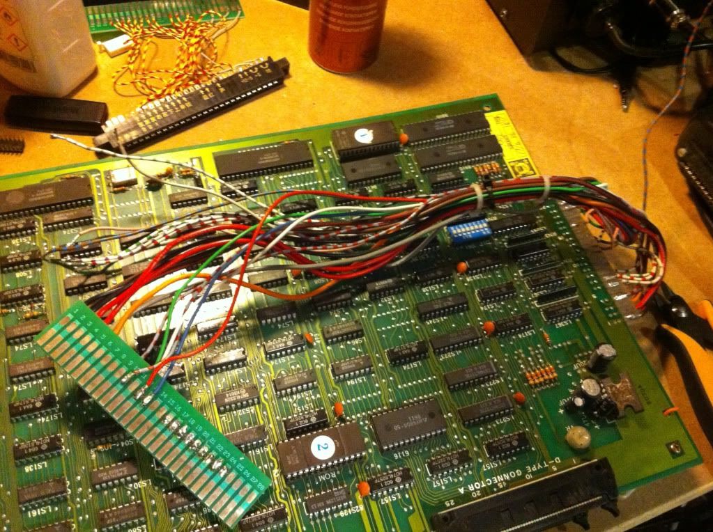
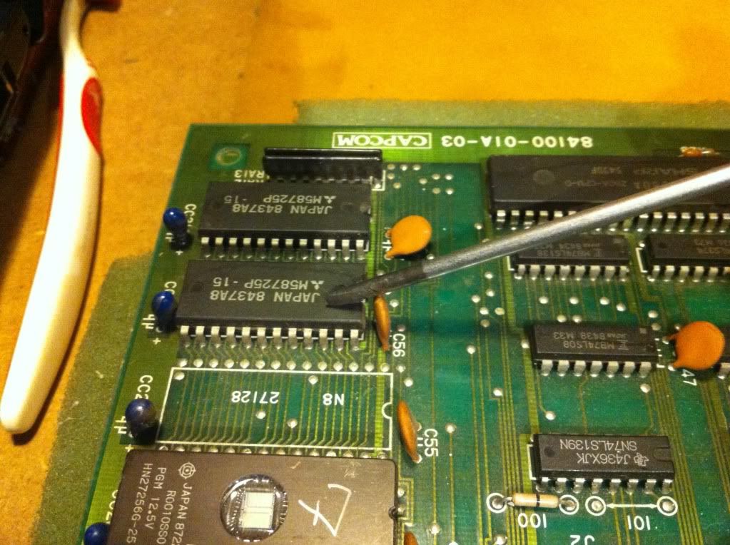
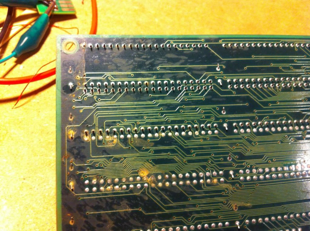
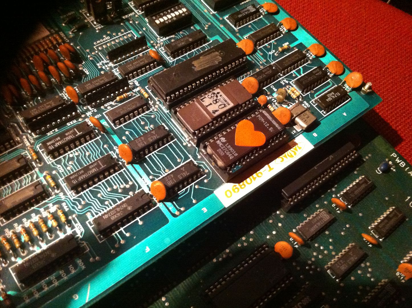
So as always, I started off with visual inspection:


and a lot of the sockected ICs (8 or 9 of them including the main CPU) had rot (corrosion) on the pins.


This can however easily be removed  by scraping the infected areas with a Stanley knife, gently rubbing it with Steel Wool, or both.


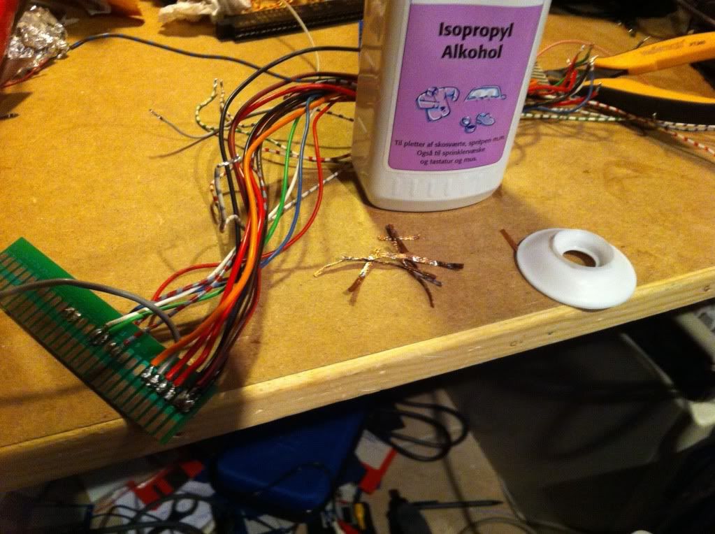
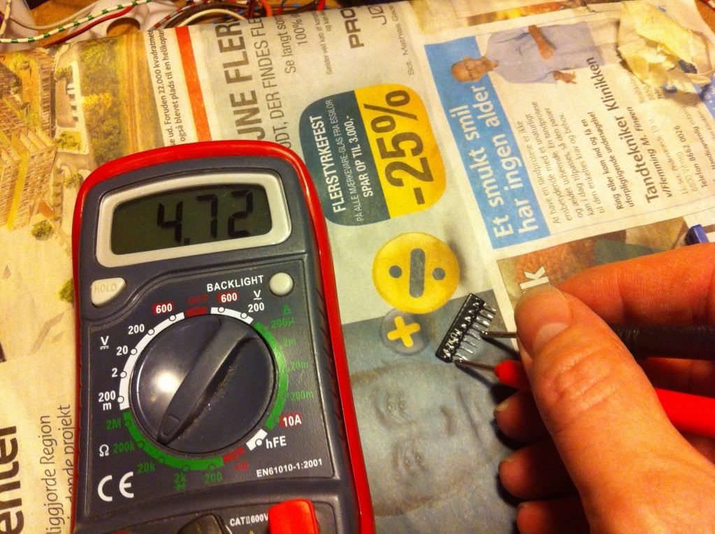
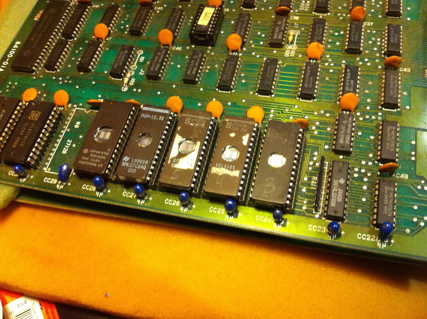
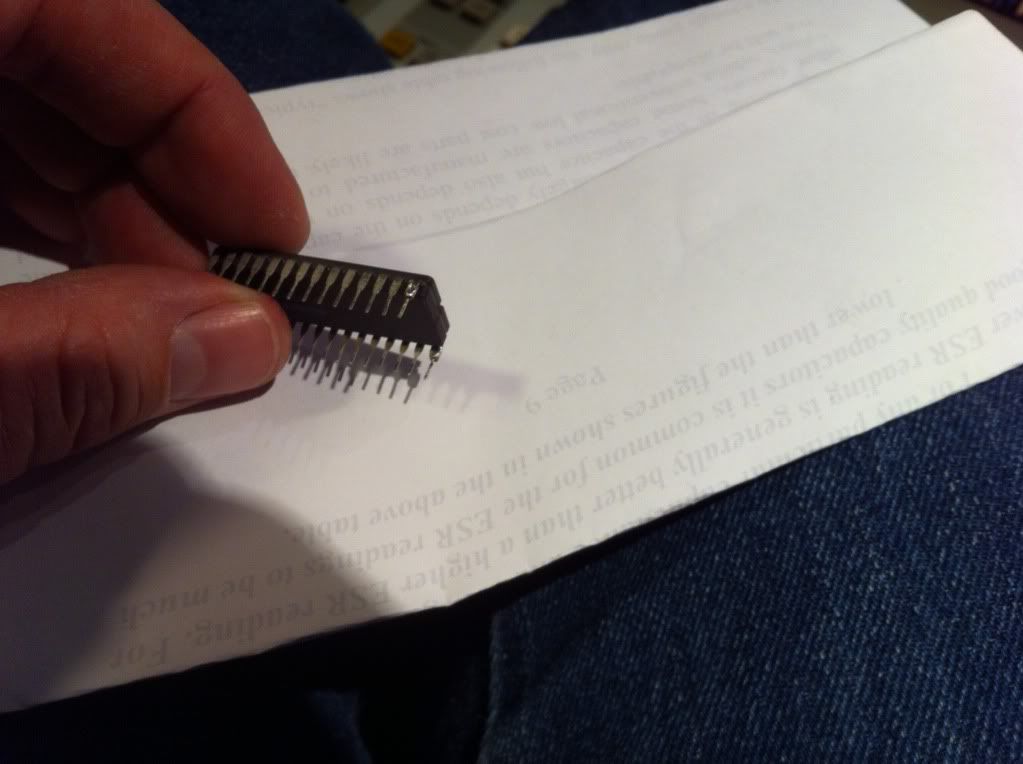
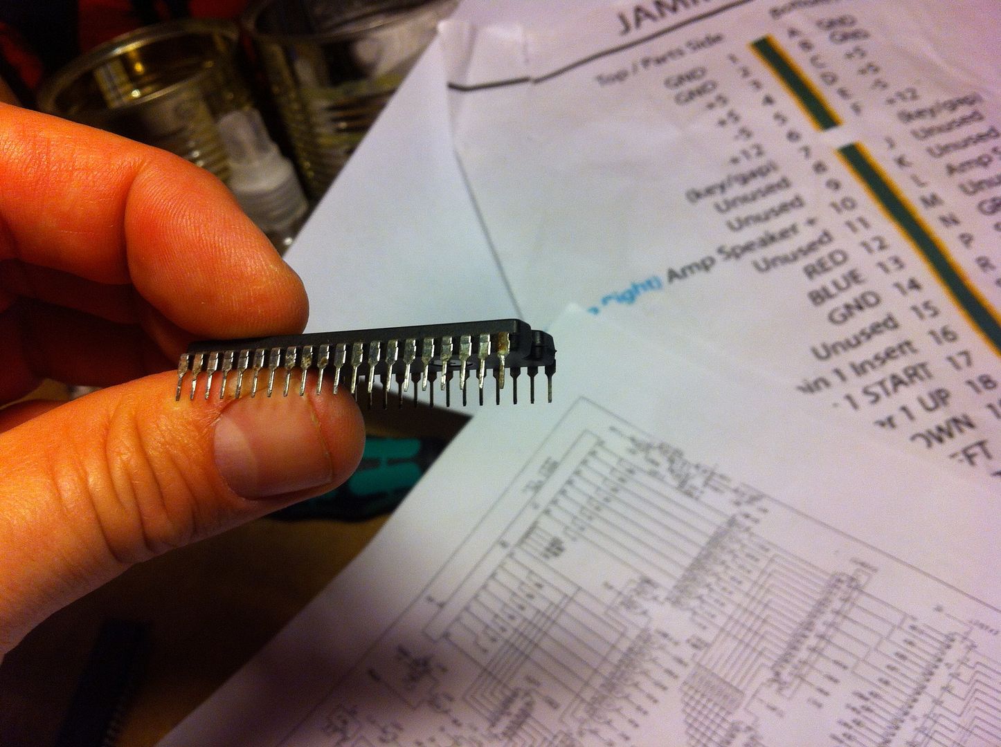
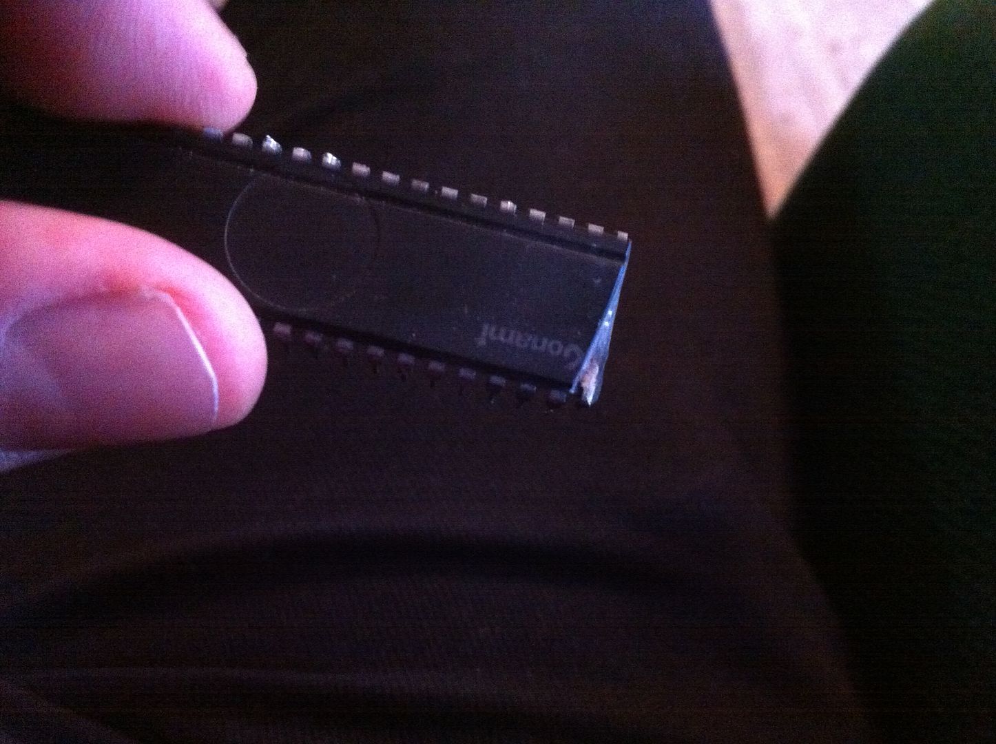
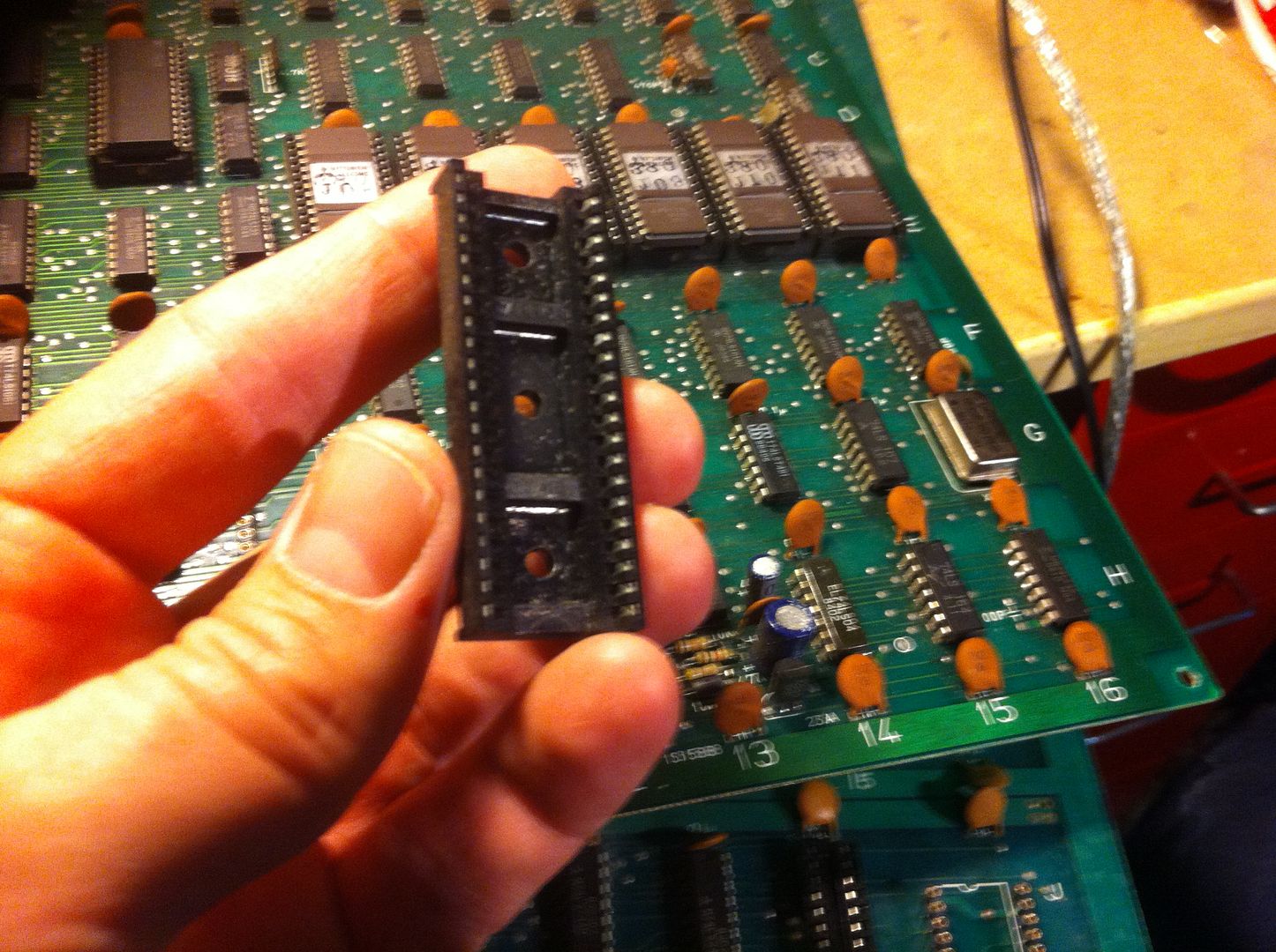
Next I started checking and dumping the ROMs on the board. And on 3 or 4 of them, pins were missing.


Luckily, it's fairly easy to patch another pin (taken from a scraped IC) on to it, as long as there's still a fair amount of pin left };-P


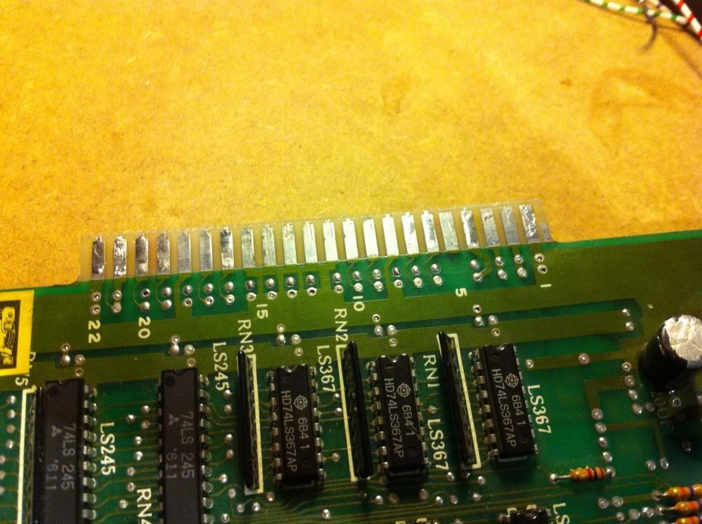
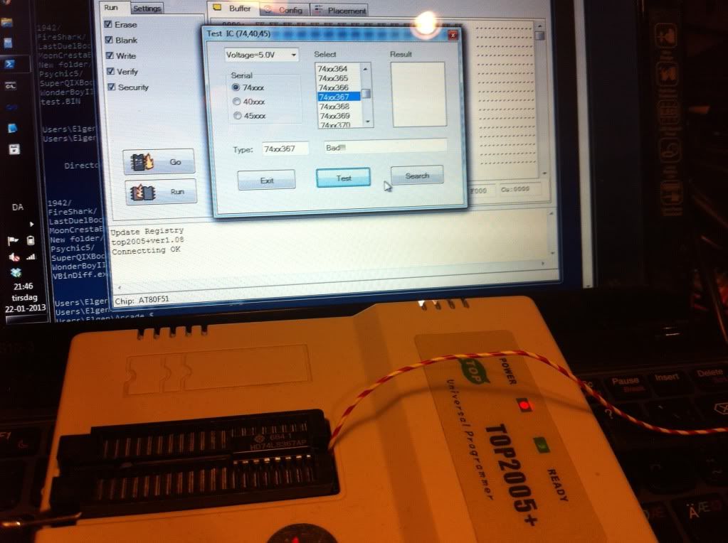
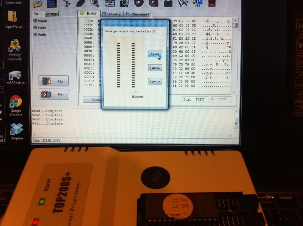
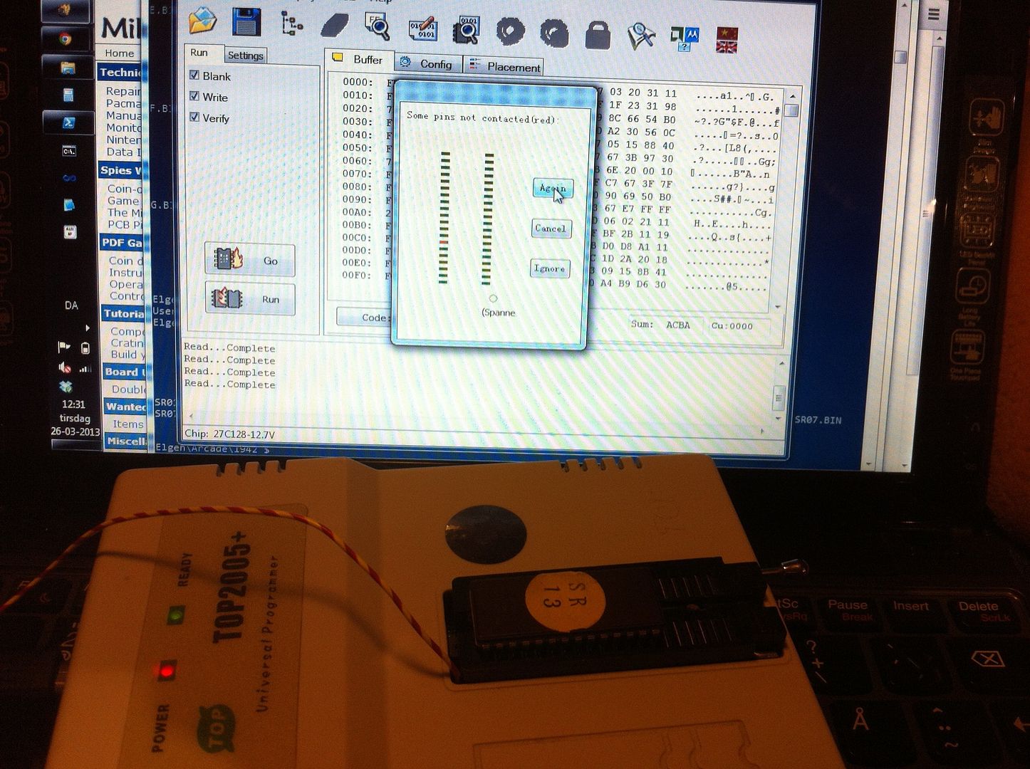
Many of the ROMs wouldn't be read in the EPROM programmer at first, but then one have to remember, that the ZIF-socket of the programmer only grabs on to the sides of the pins. So if the pins are rotten, it's important also to clean the sides as well. So when I'd cleaned the sides of the pins, all but one could be read and verified against MAME. It was one of the 2 EPROMs in the sound section that seemed to be knackered, so burned a new one and smacked it into the socket.


I now tried to connect the board again to see if there was any change, but still black screen and sound.
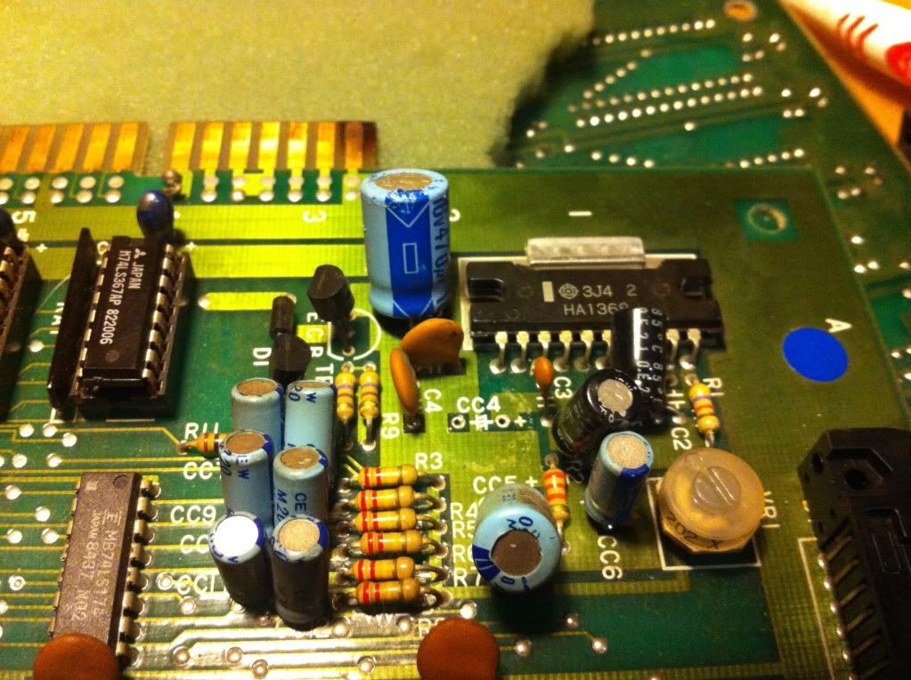
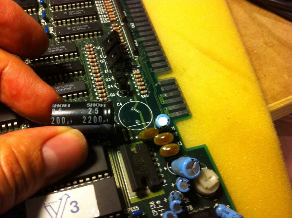
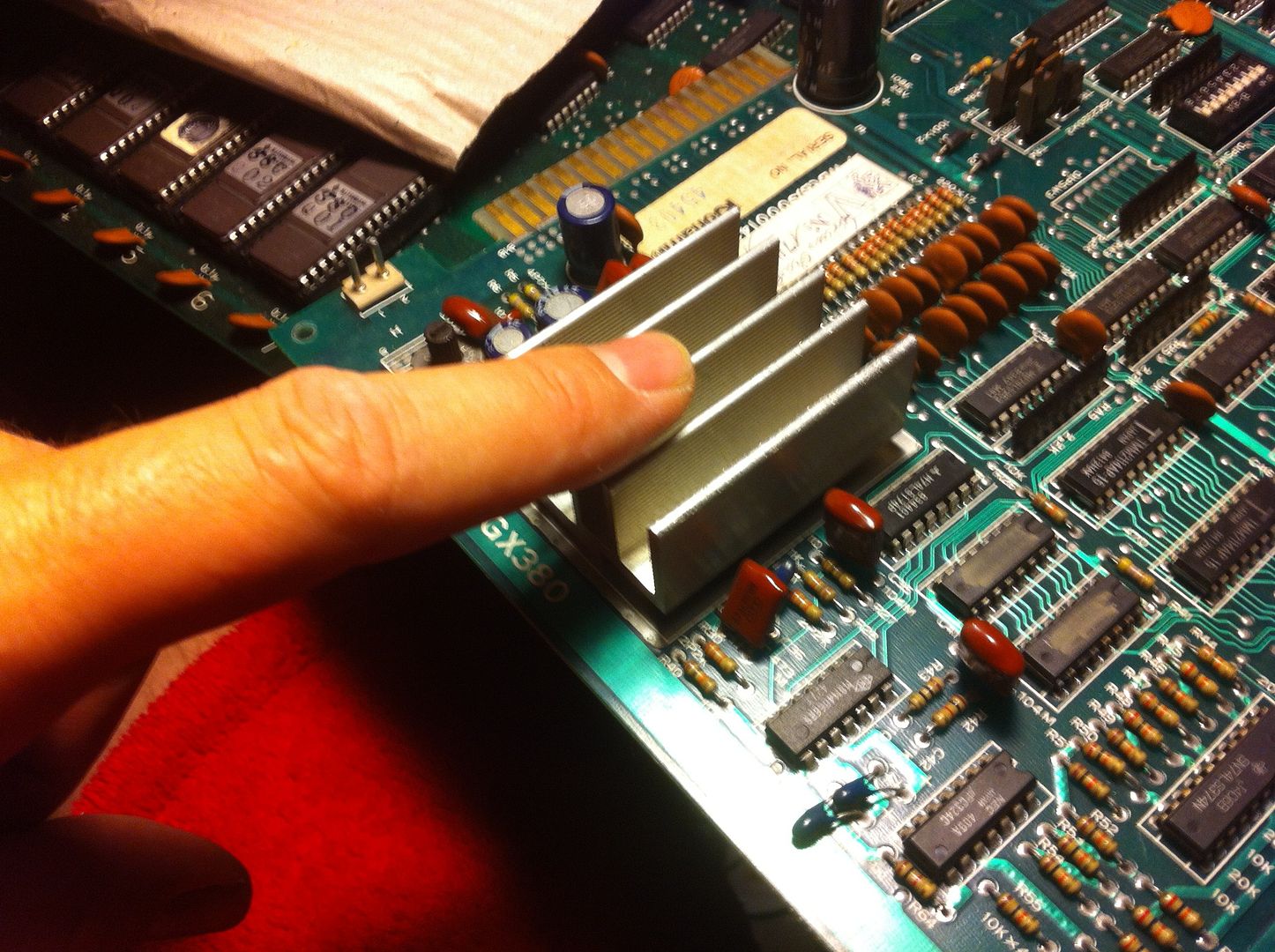
Next step was to start measuring on the poor board to see what might be wrong. However, after having the board connected for just a minute or so, a smell of fried electronics started to emerge. I quickly found, that the AMP was burning up; almost gave me blisters when I touched the heat sink.


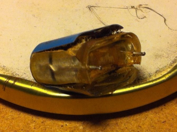
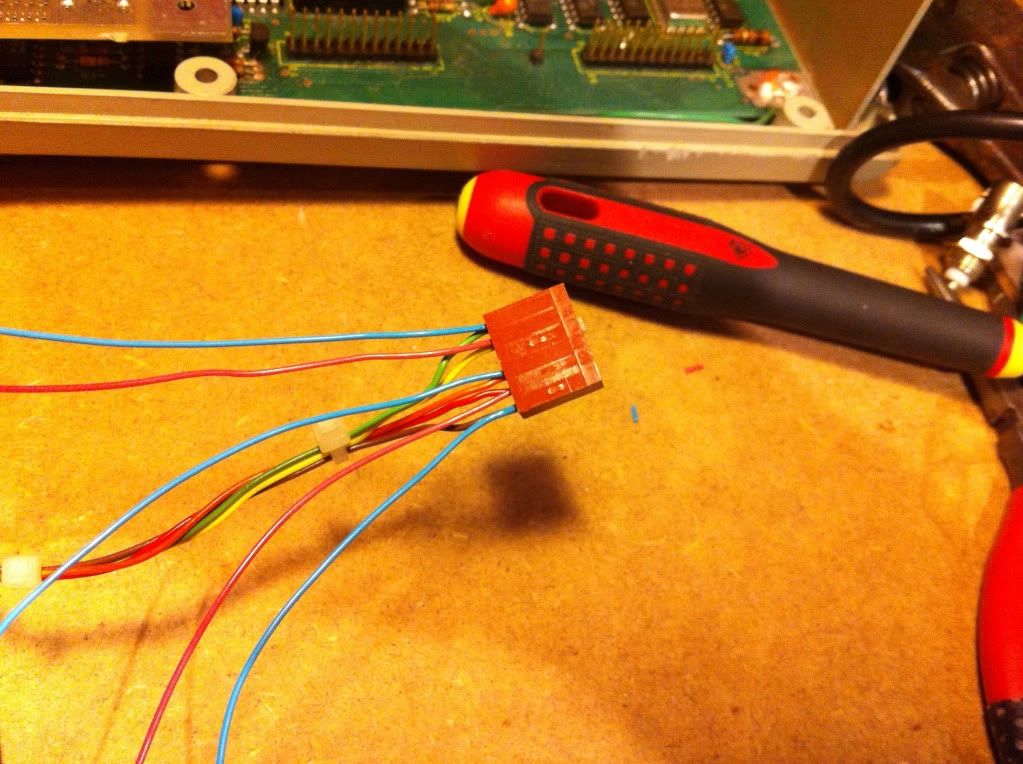
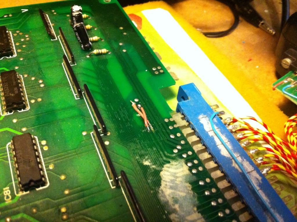
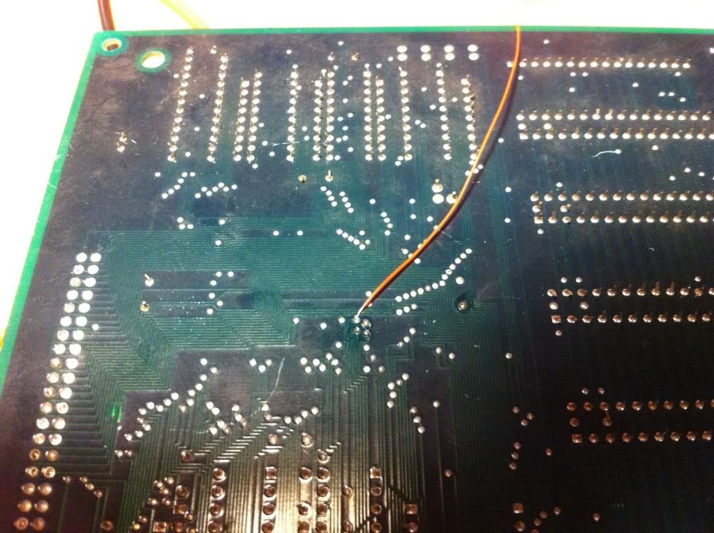
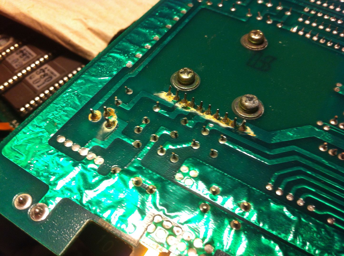
I turned the sub PCB around and found that the soldering for the AMP and the sound pot didn't look so good.


So desoldered both components for now so no further harm would be done and to move onwards with waking up this game.
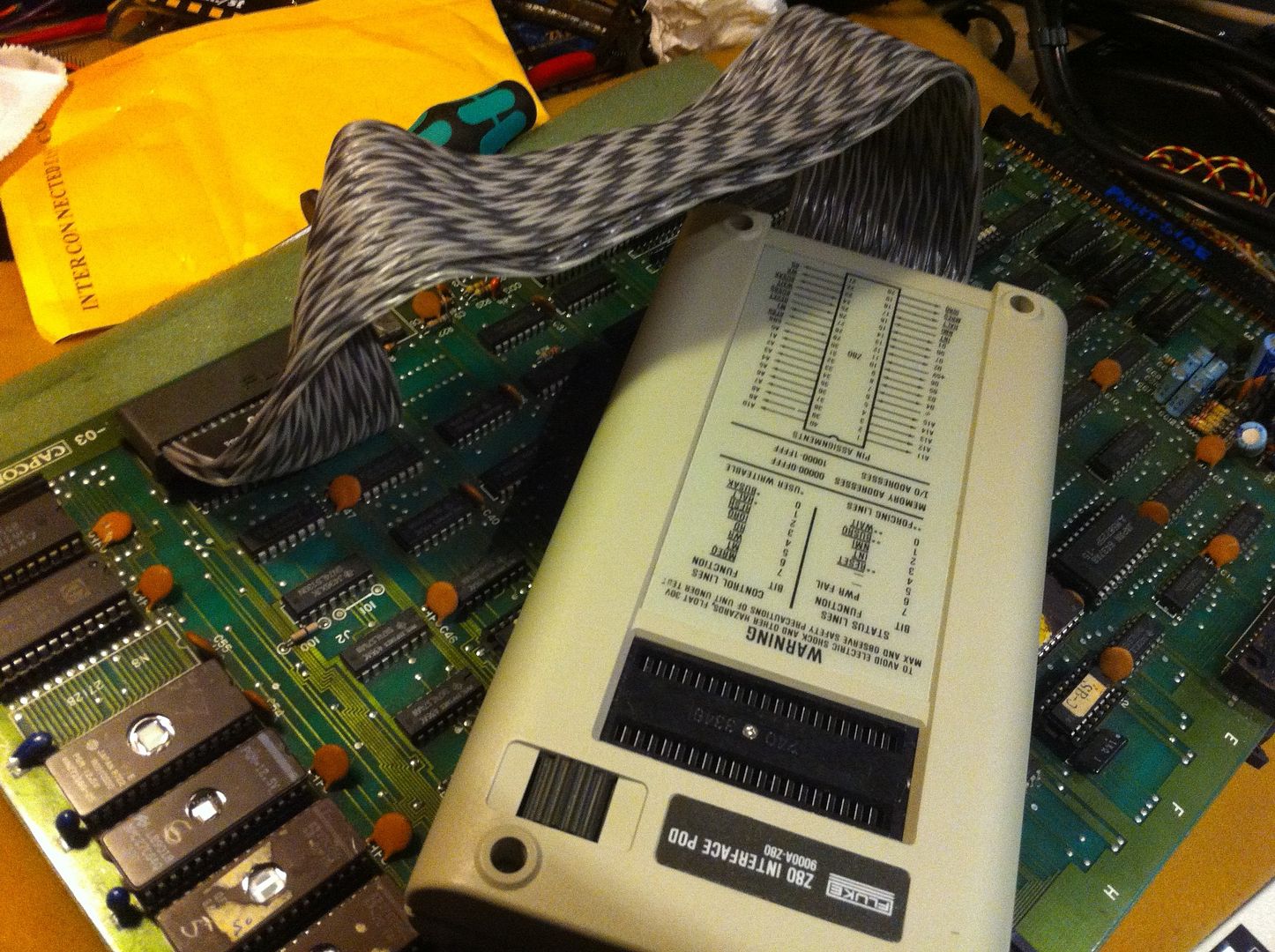
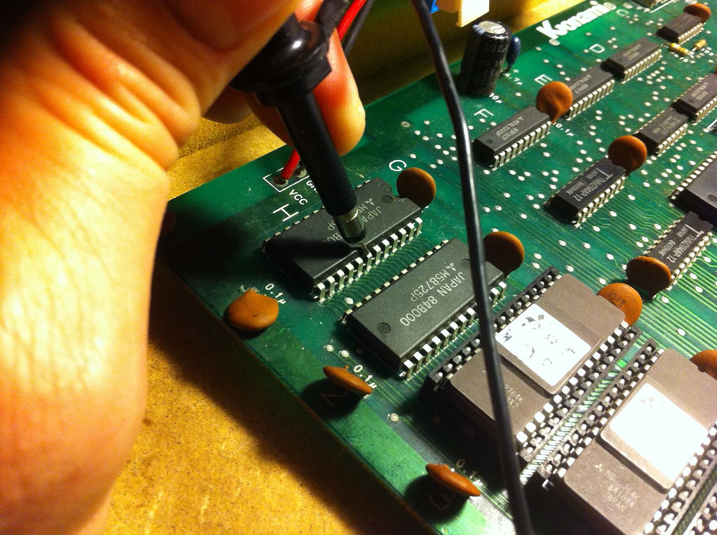
Armed with the schematics for the game and my scope, I started with the CPU. This game (as well as a number of other Konami games from this period) has a custom CPU called Konami-1. It's basically a Motorola6809, but with scrambled opcodes and a different pinout. However with the schematics in hand, it was pretty easy to find the different control pins as well as the address and data bus.
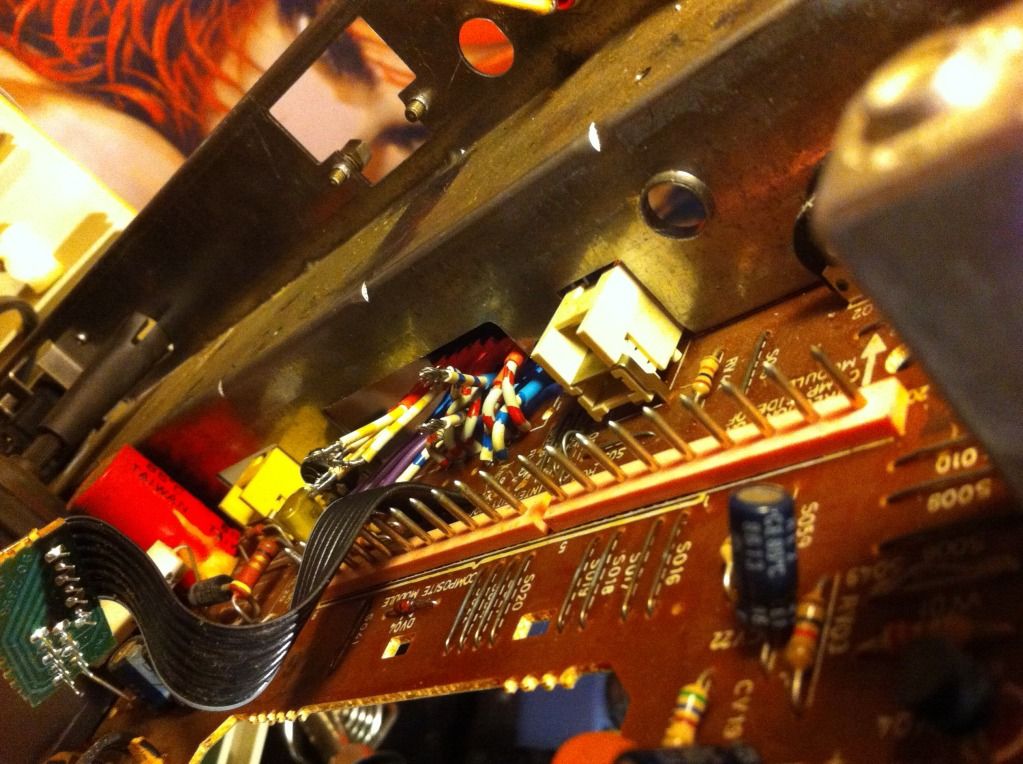
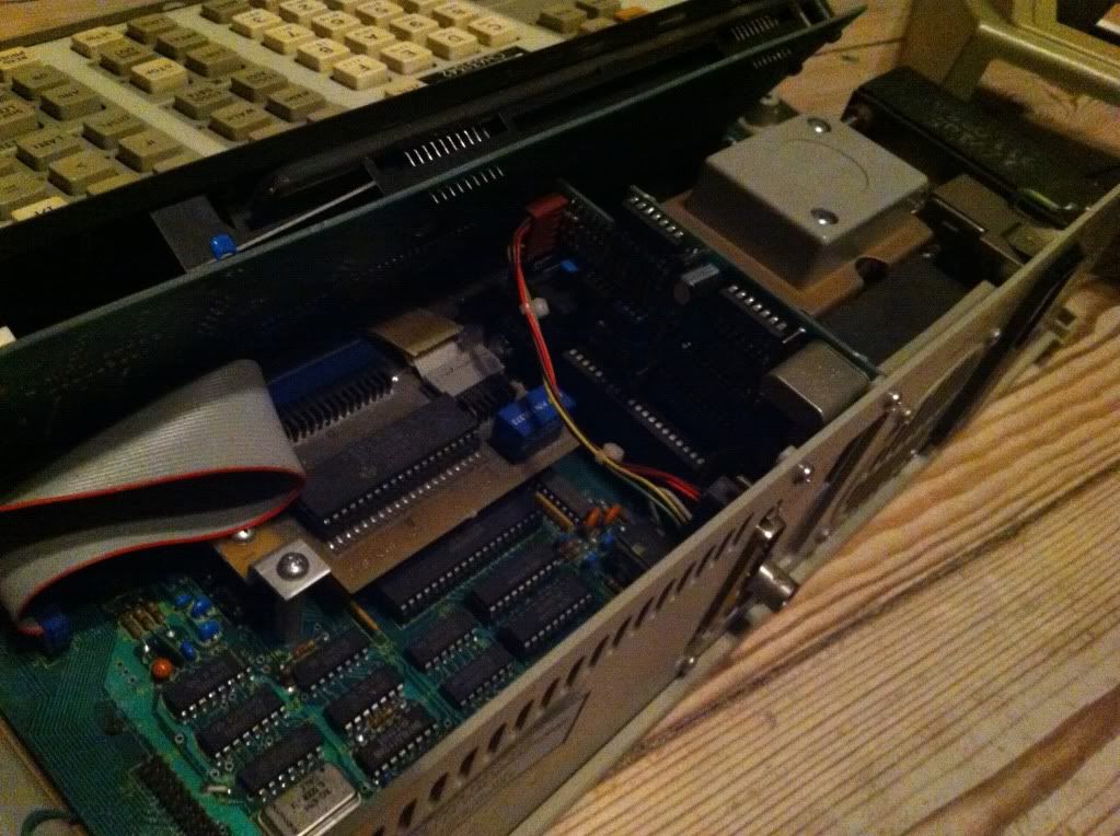
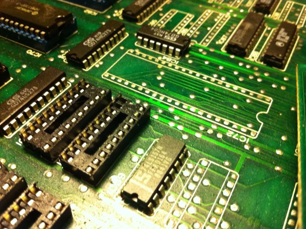
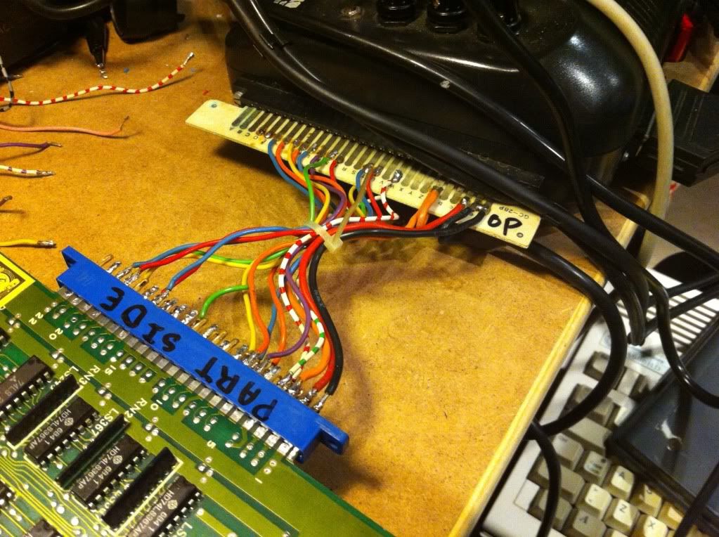
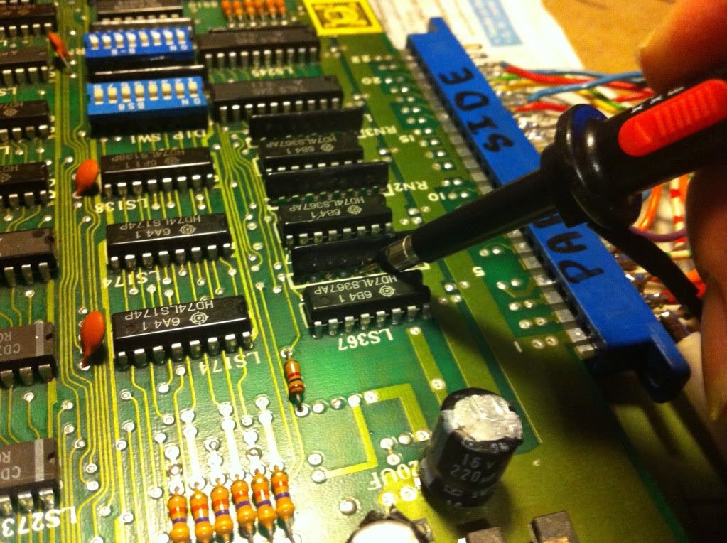
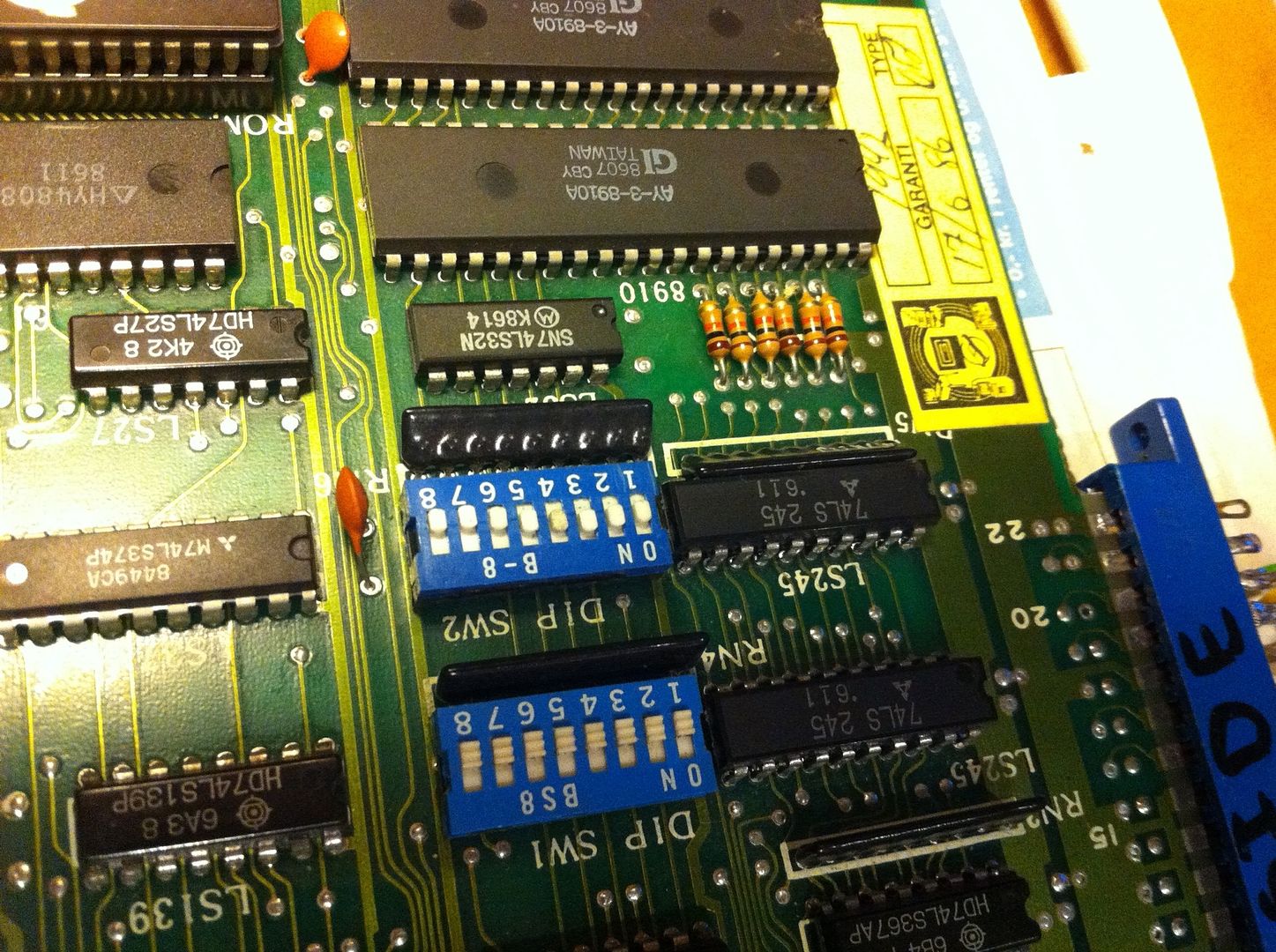
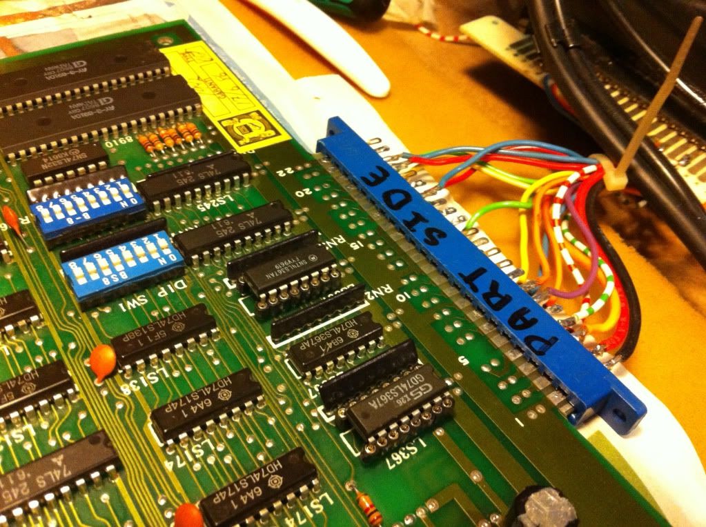
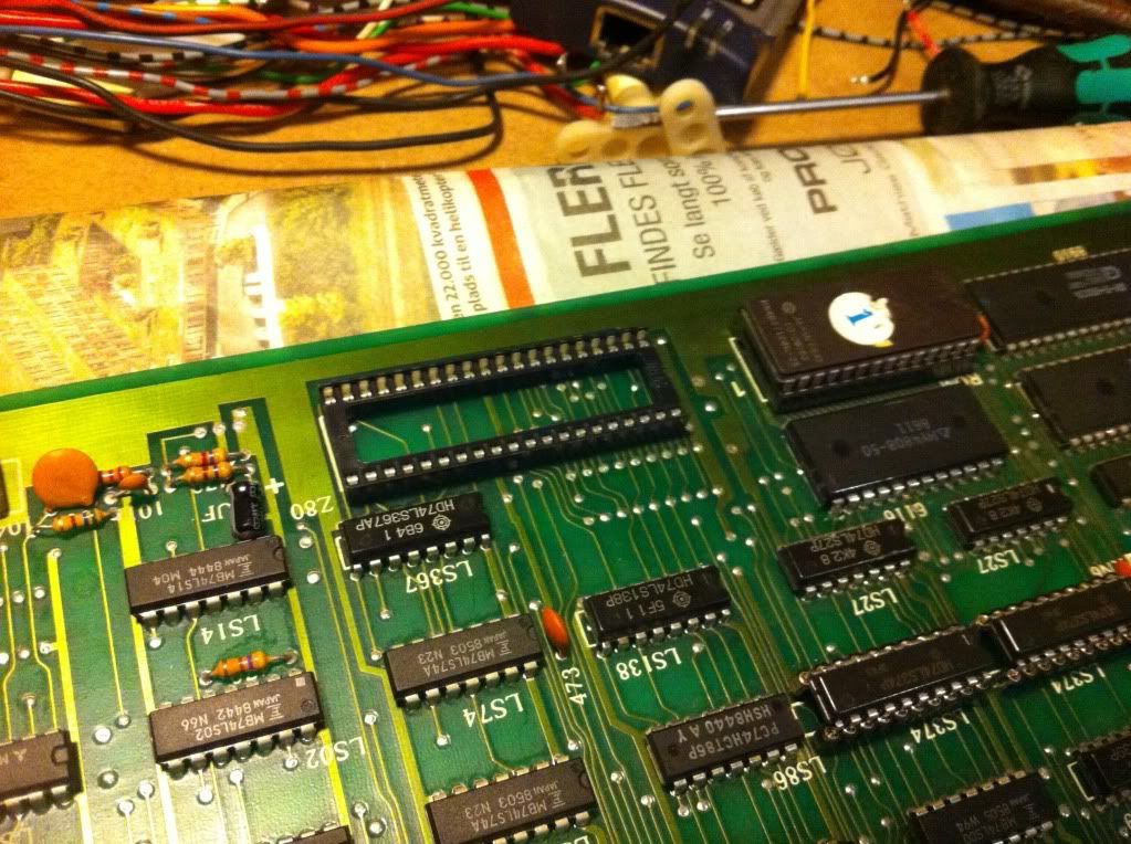
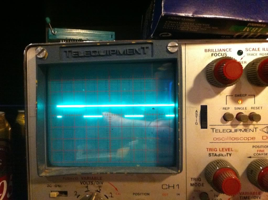
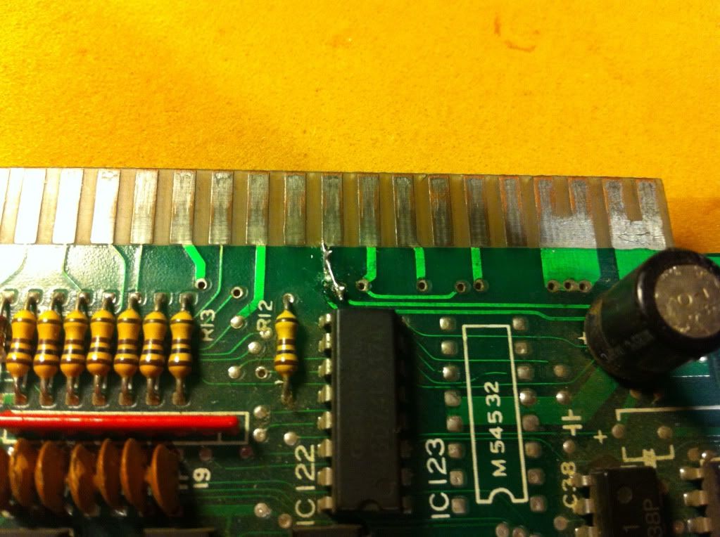
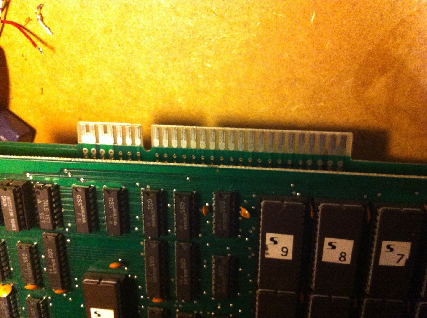
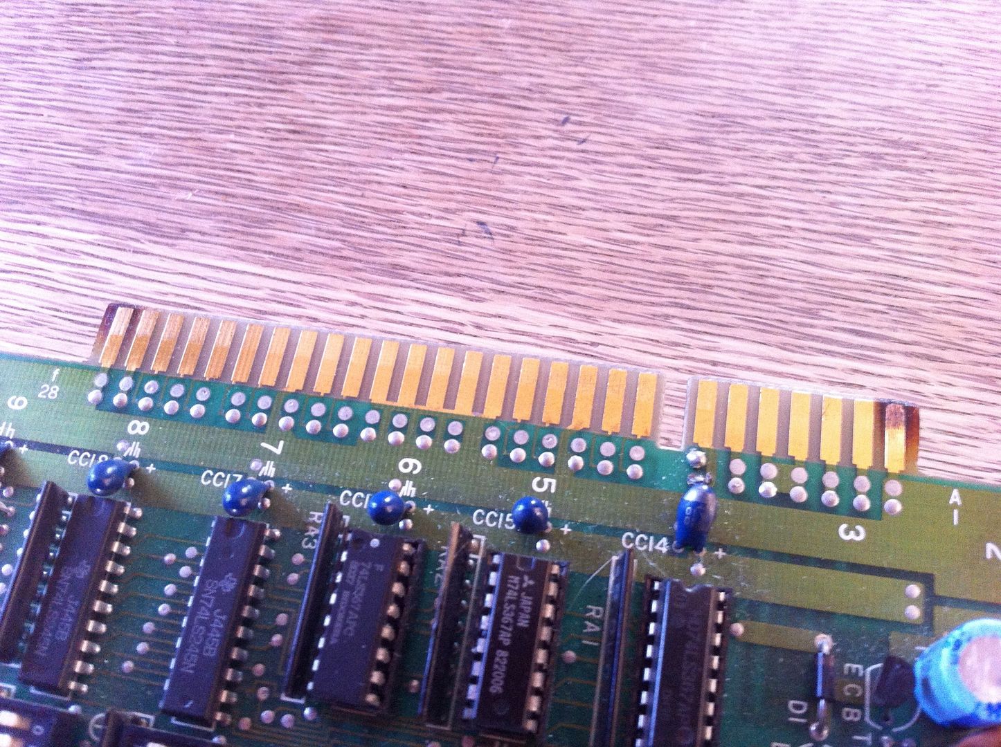
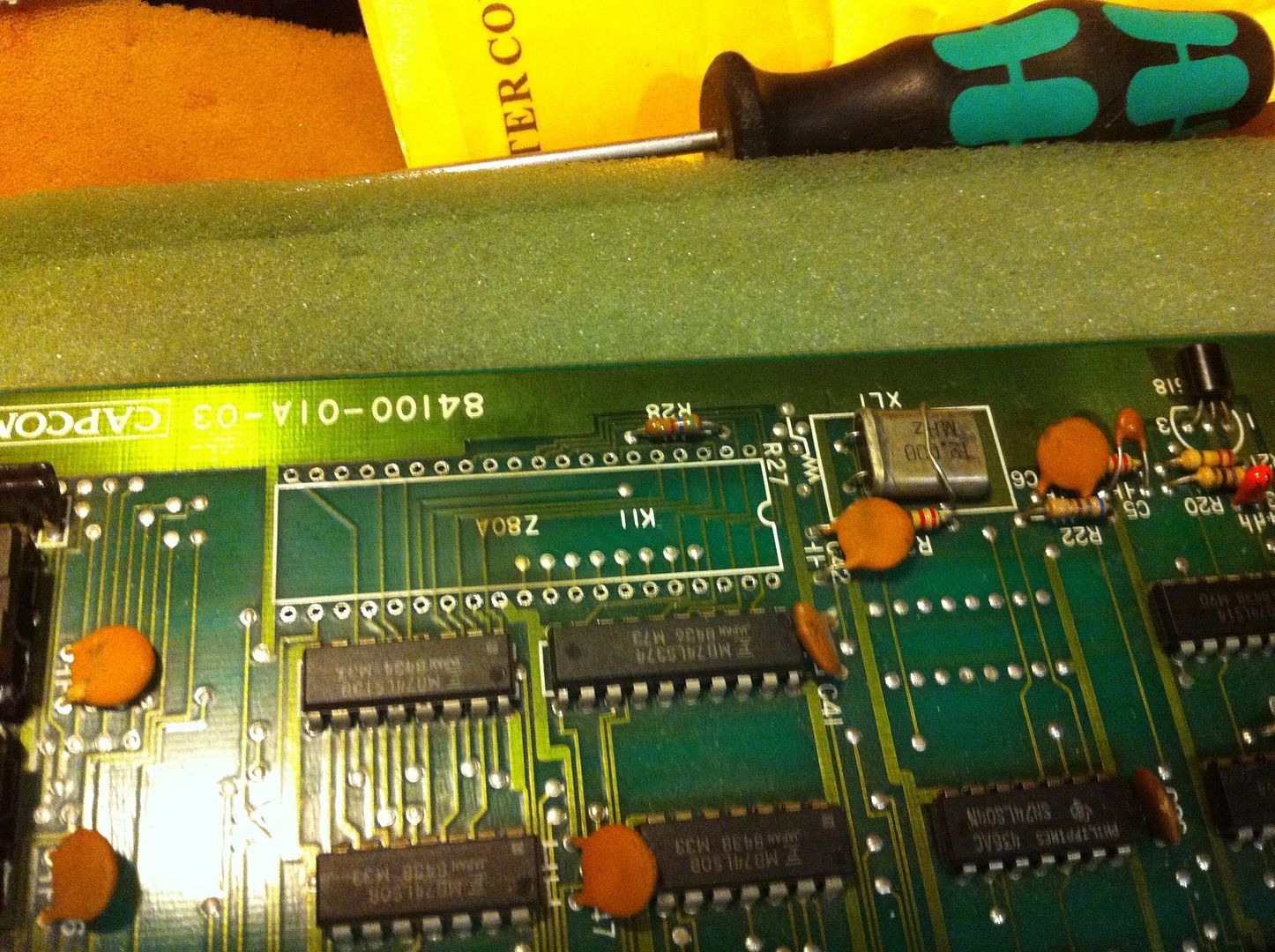
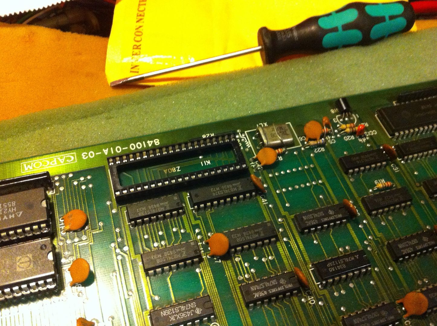
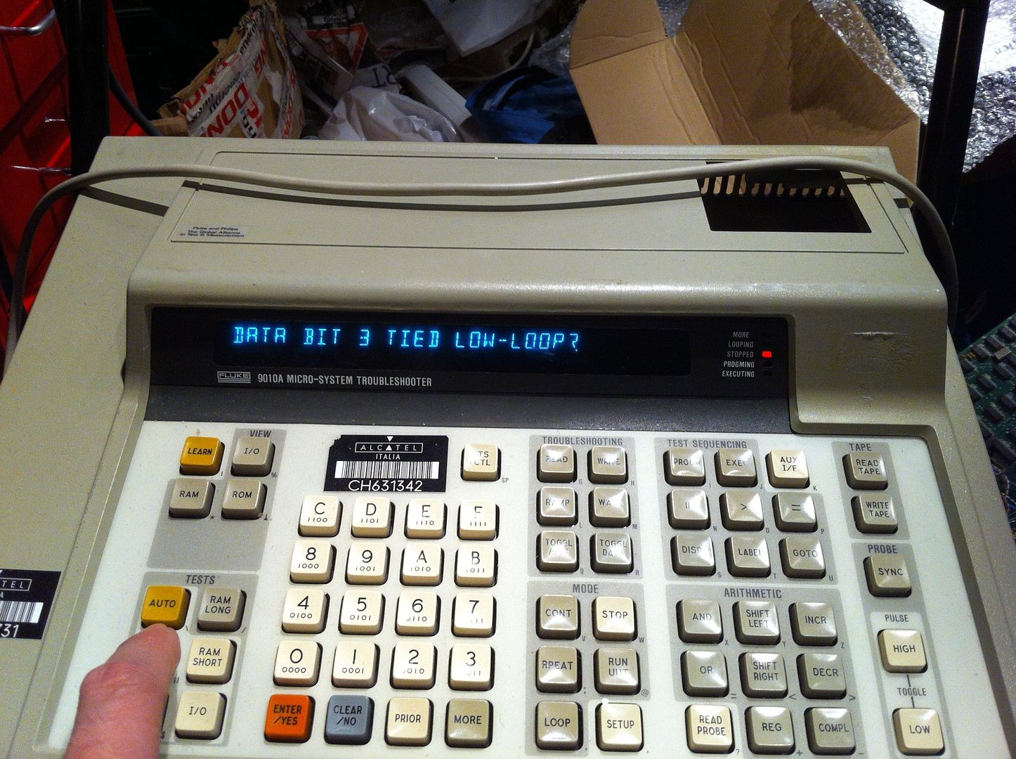
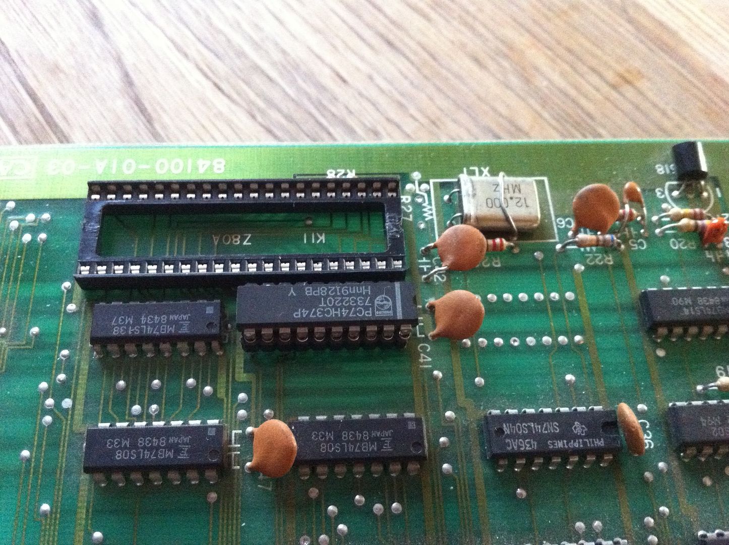
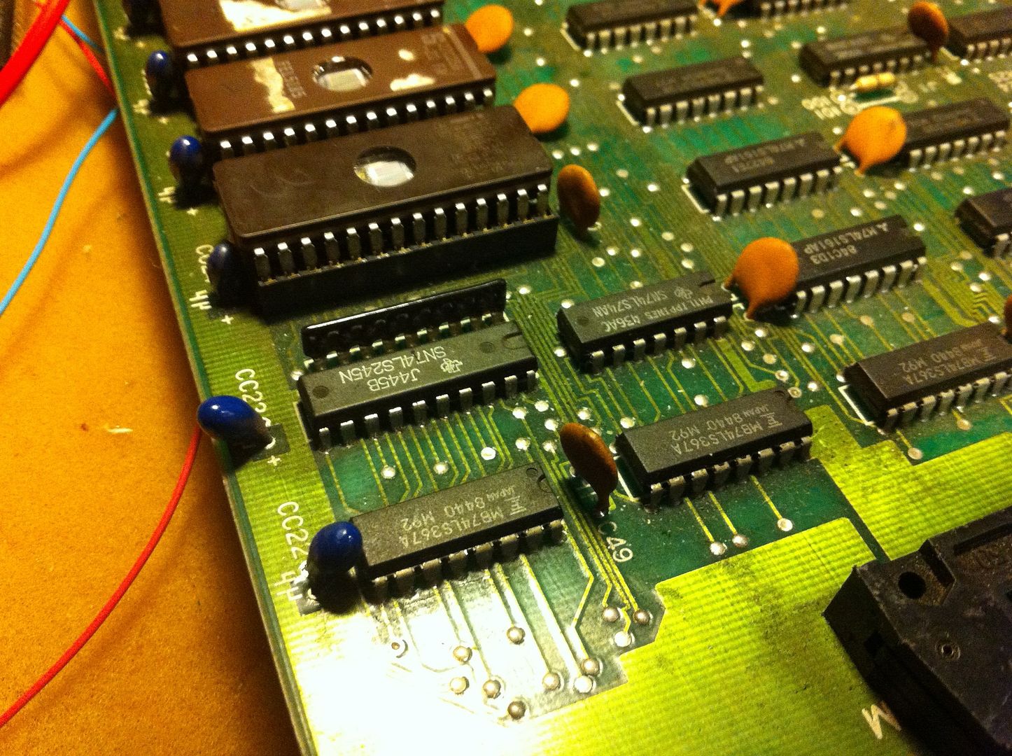
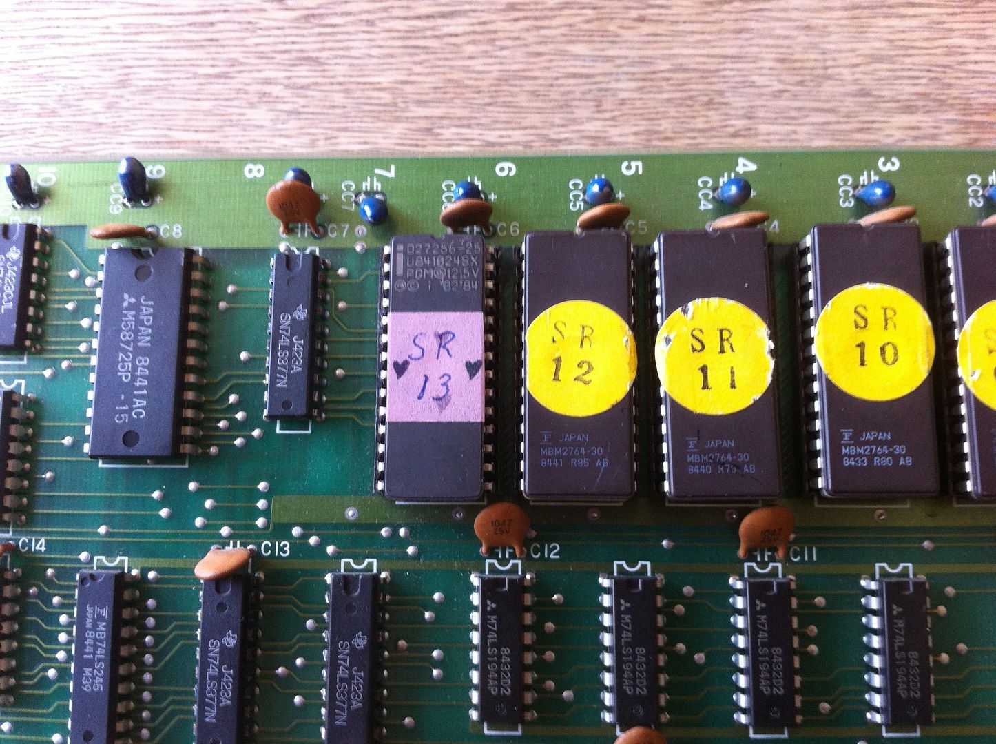
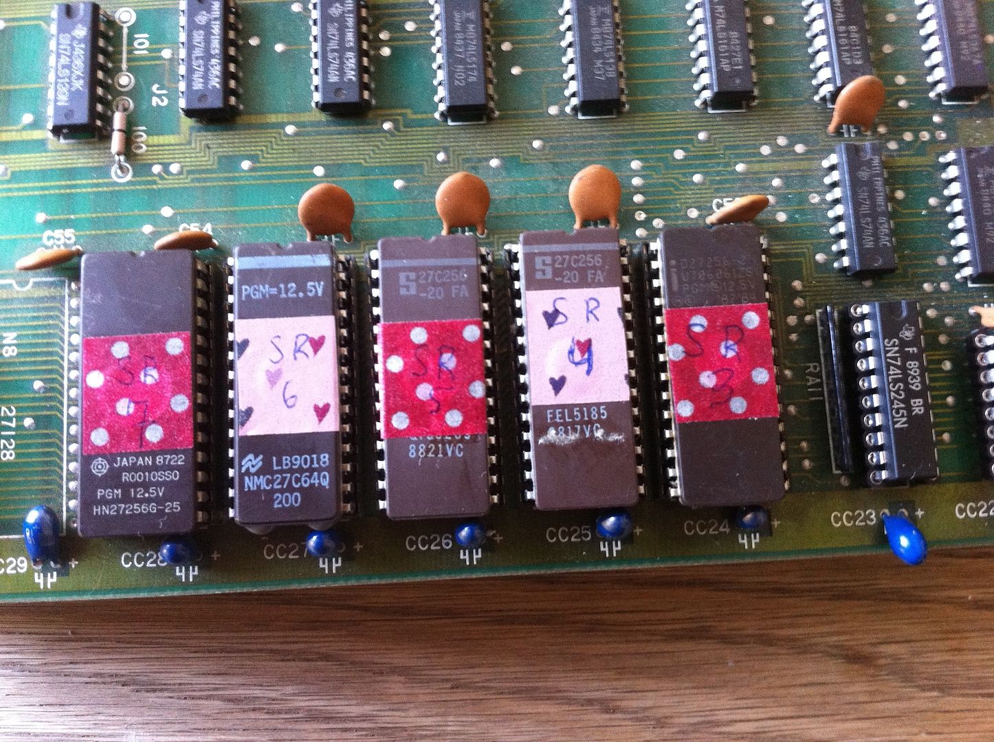
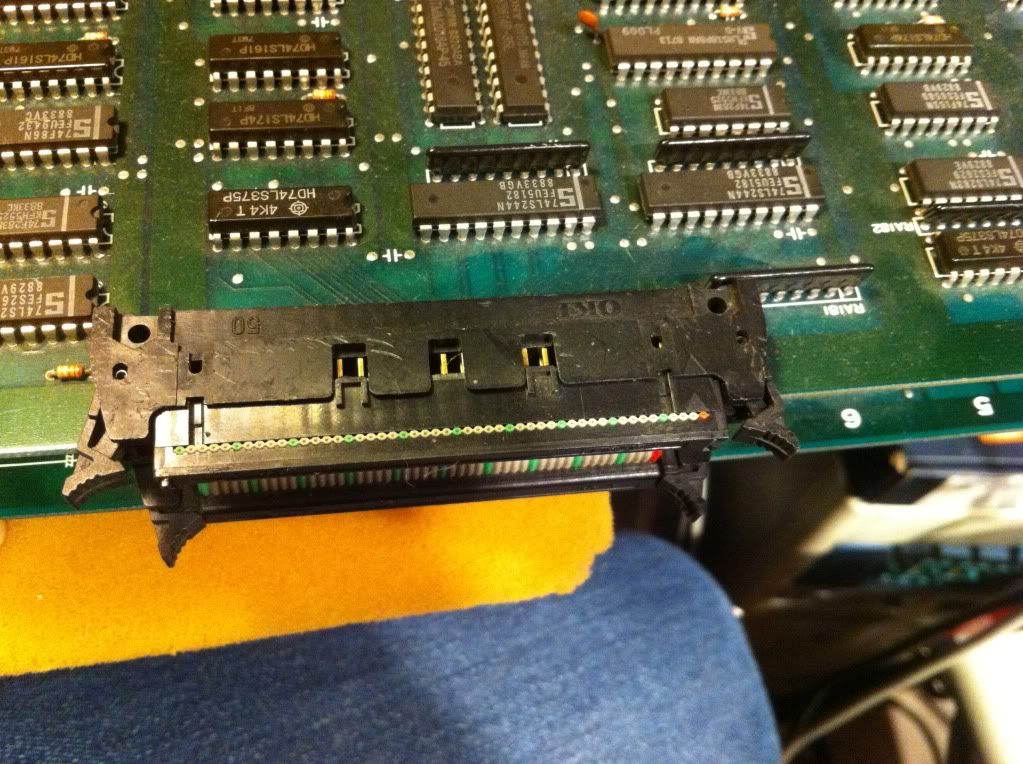
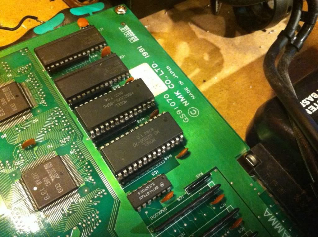
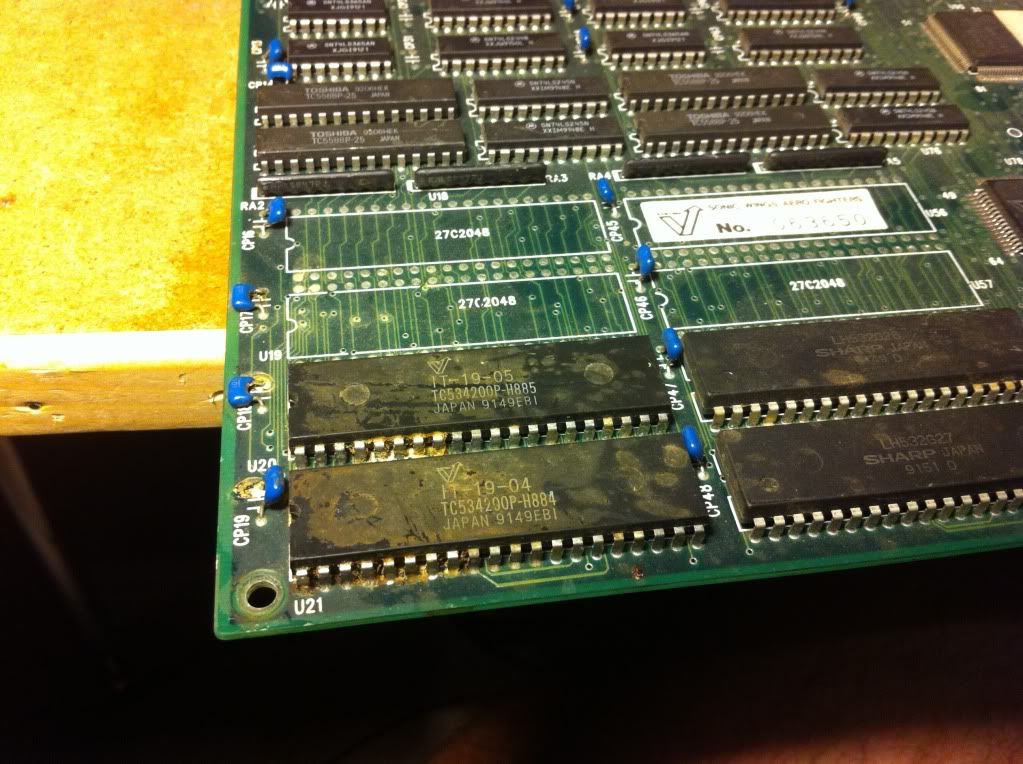
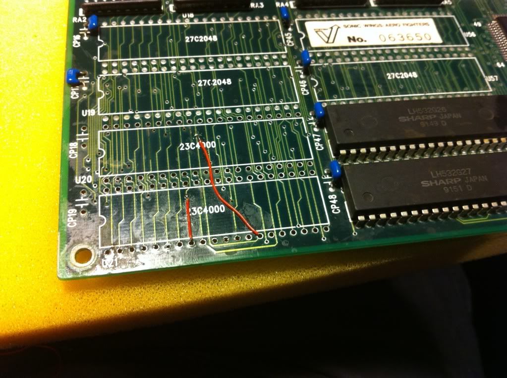
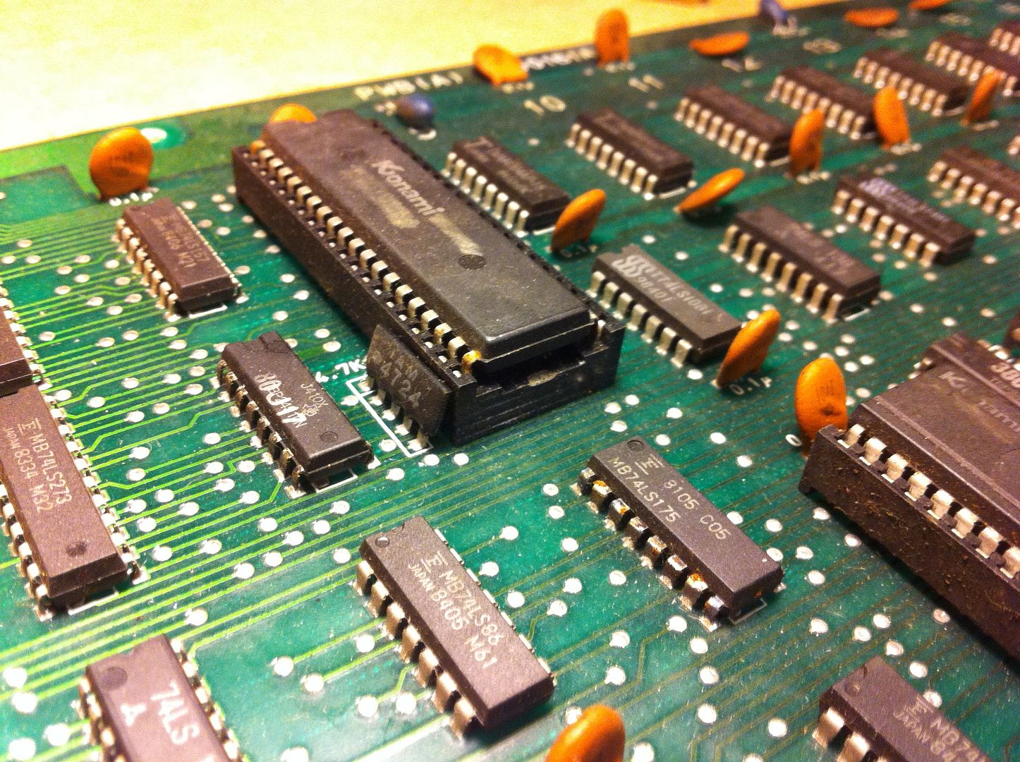
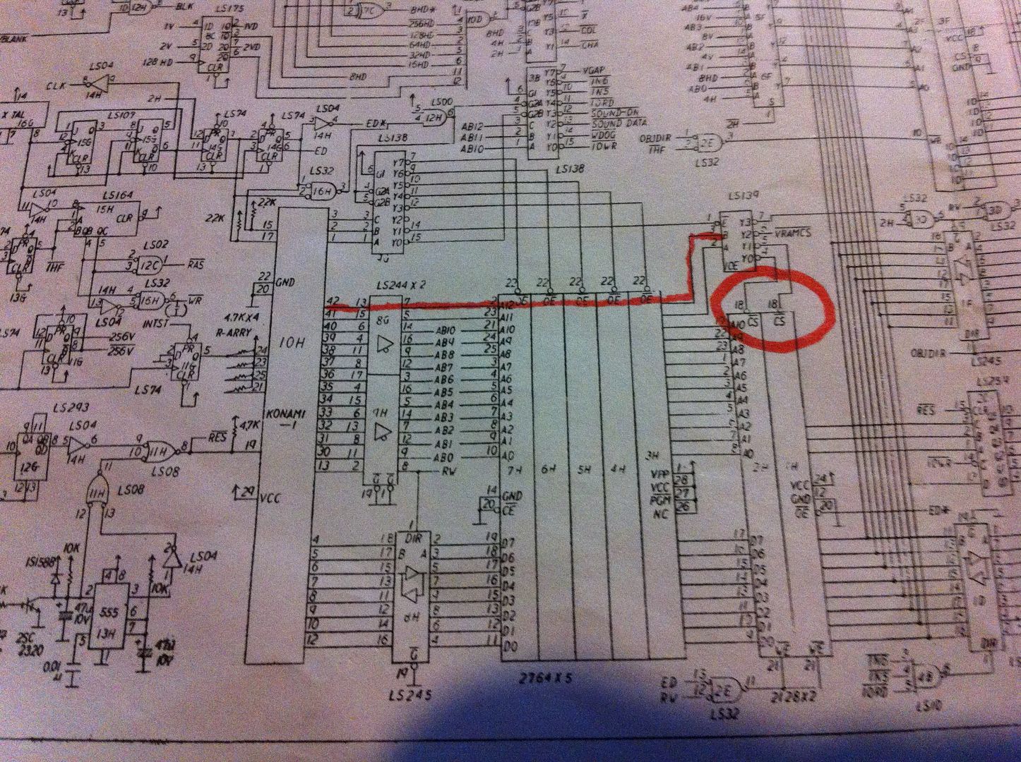
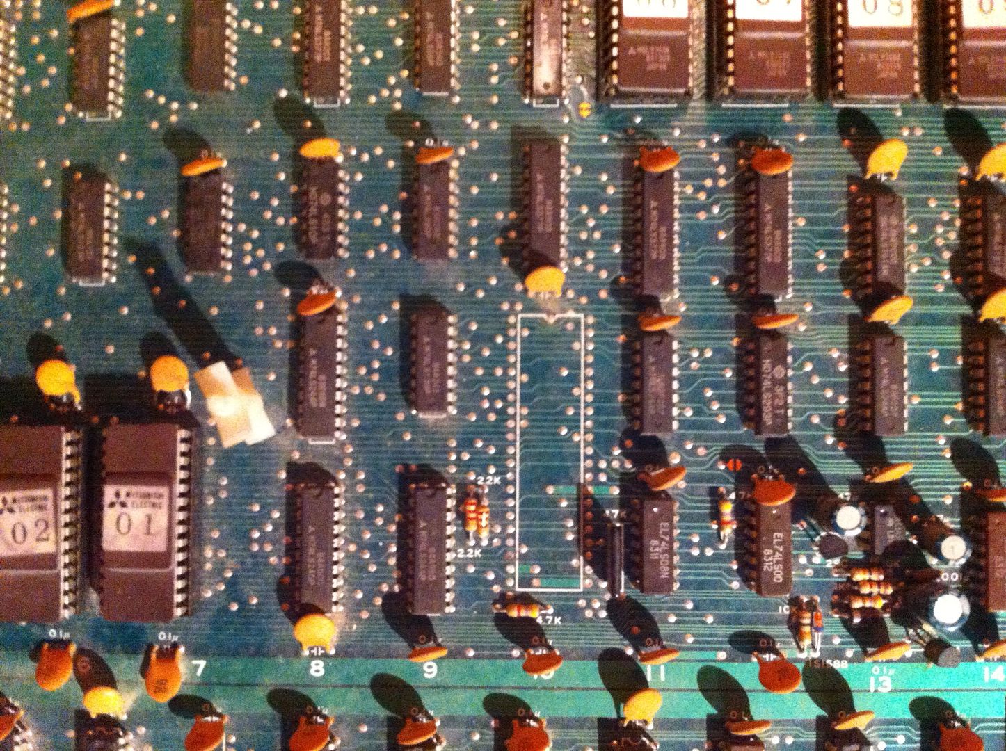
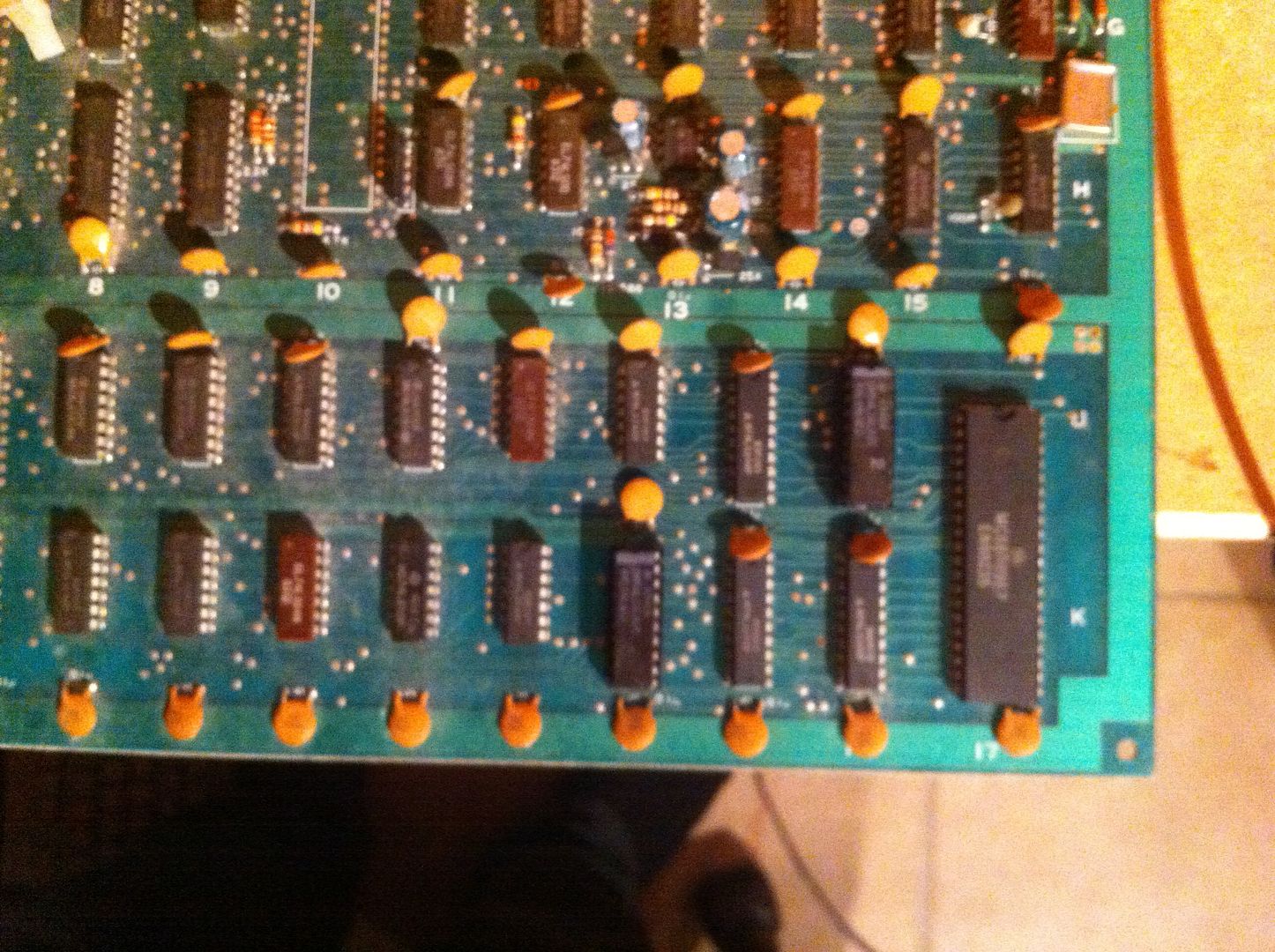
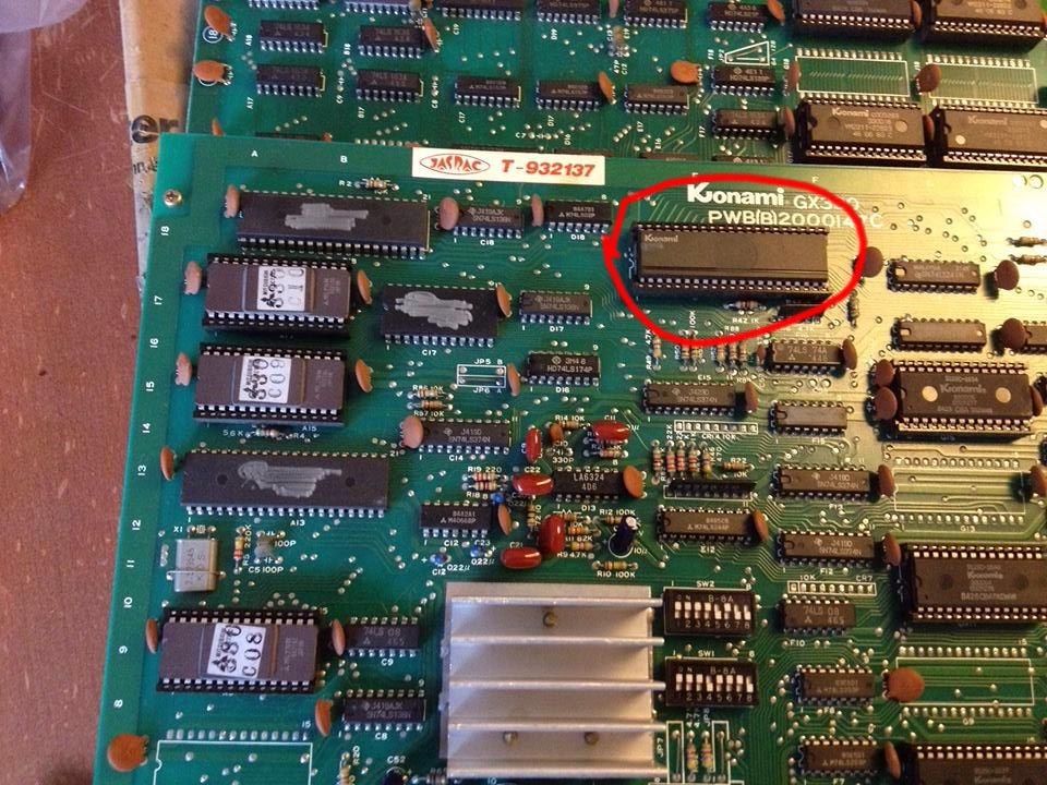
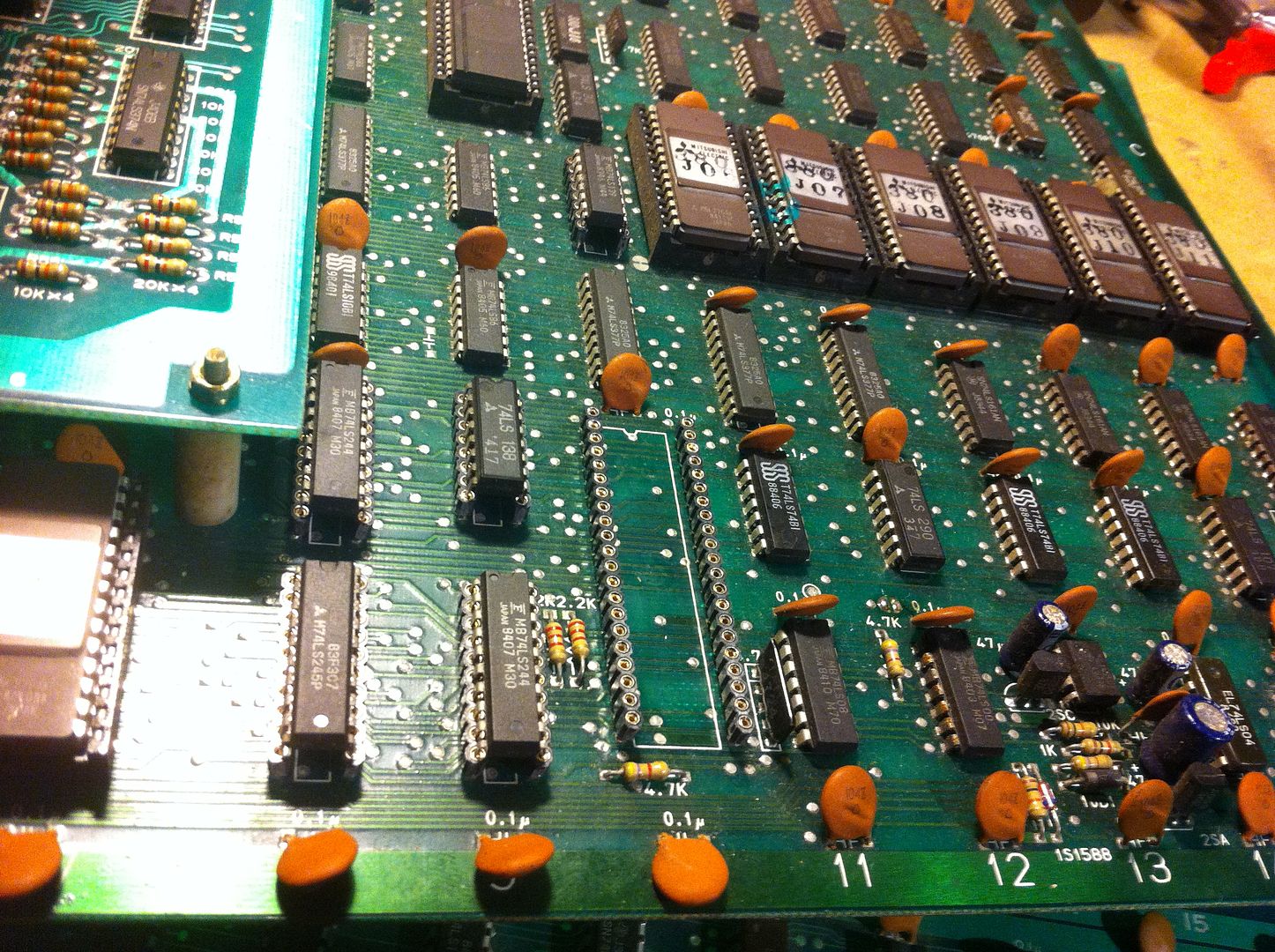
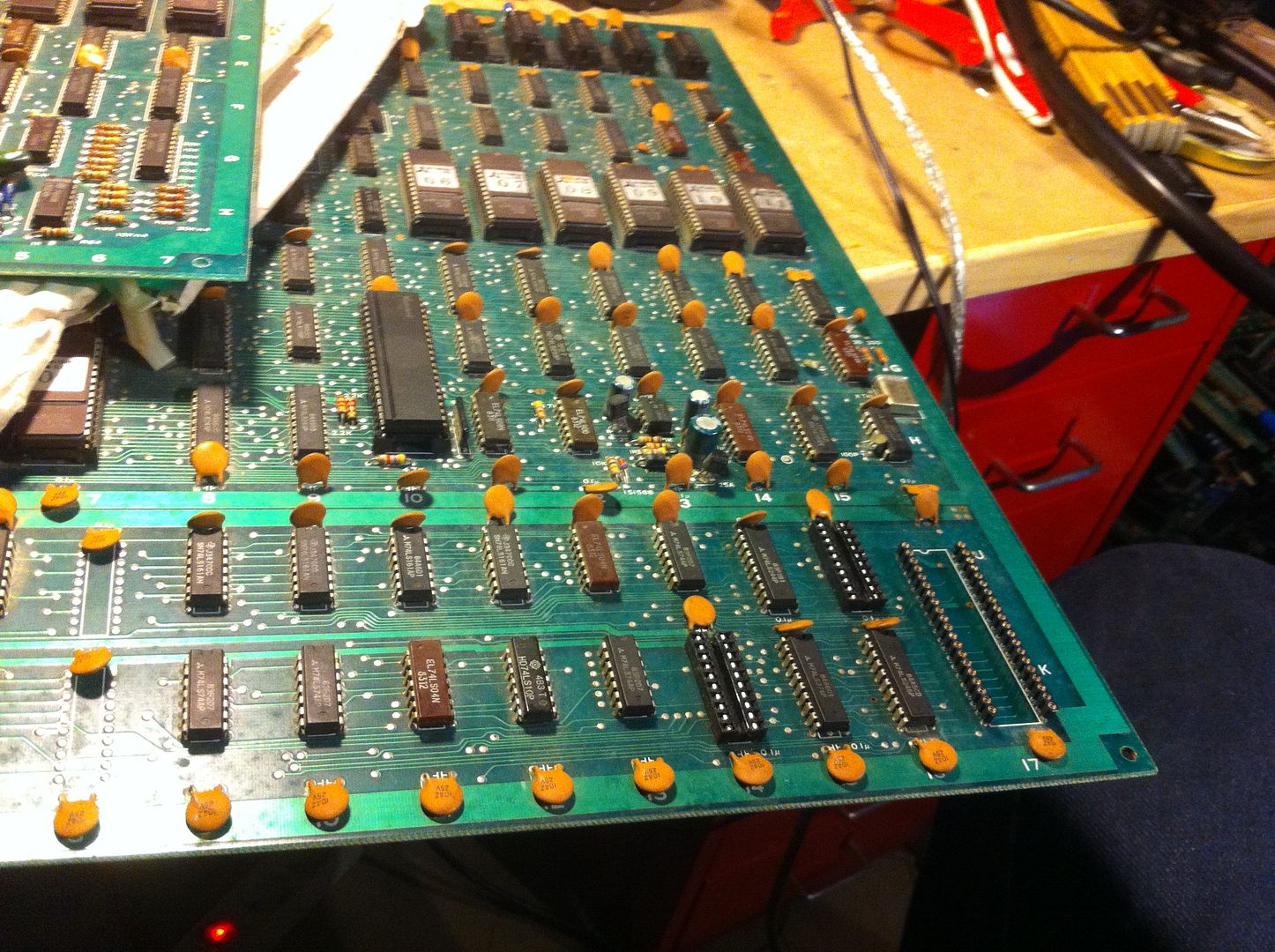
The CLOCK signal was fine, but the RESET pin was pulsating, indicating that the watchdog was barking. Looked at the data pins and they all to had some activity within the watchdog cycle. But when checking the address lines I found that the most significant bit of the address bus was stone dead, not even jumping just a little bit when power was applied; all the others did. This is pin 42 on the CPU and besides being a normal address bit for the program ROMs, it also takes part in controlling the CS (chip select) signals for the 2 scratch RAMs (indicated in red in the pic below).


I tried peeking the CS of the 2 scratch-RAMs, and one of them (the one on the left) was never selected as I suspected from the schematics and the dead pin 42 on the CPU.


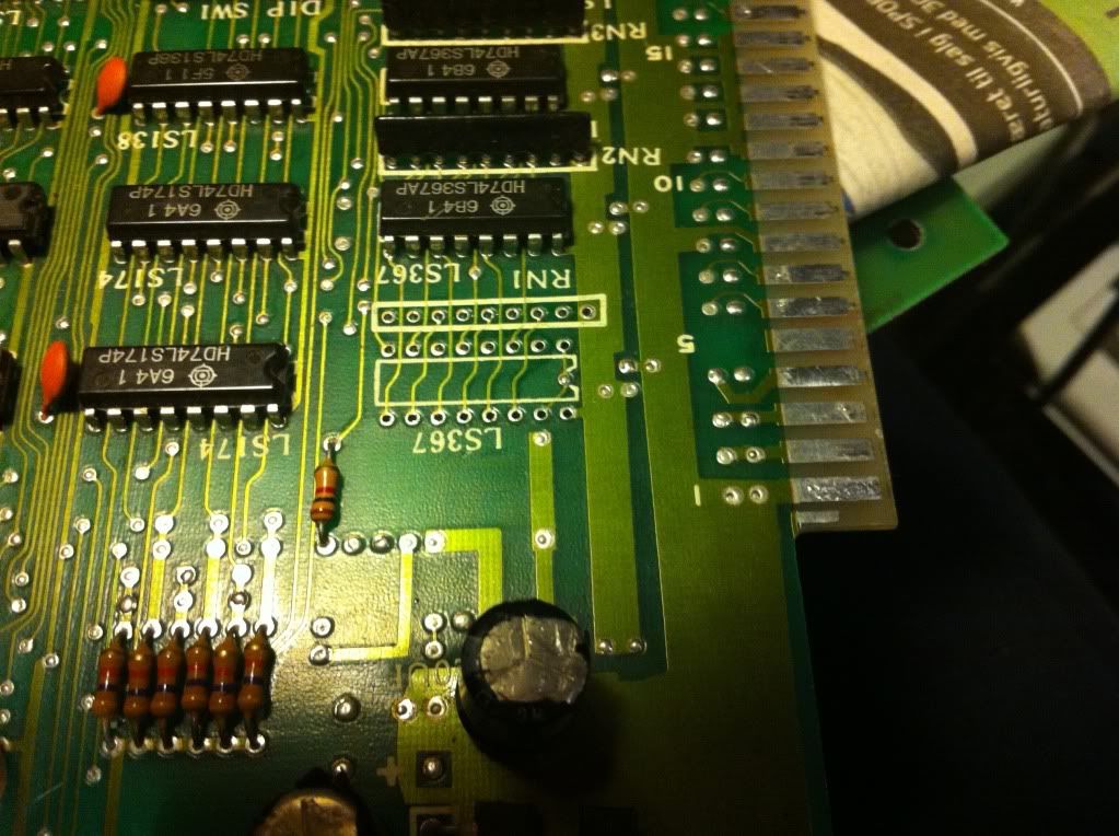
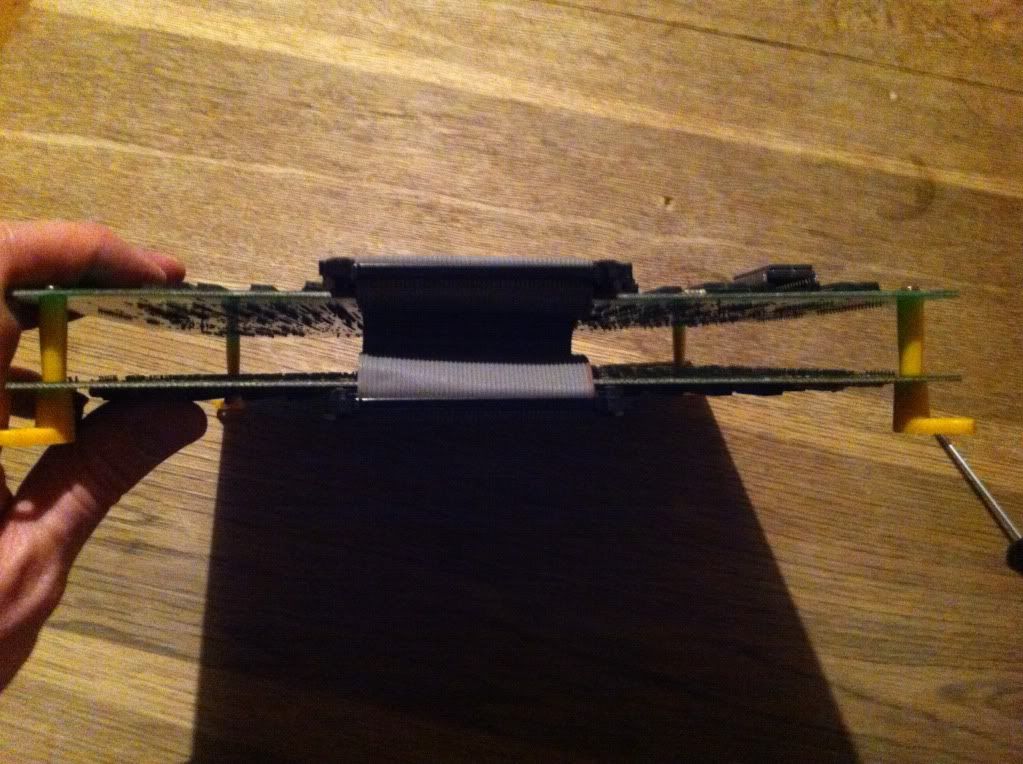
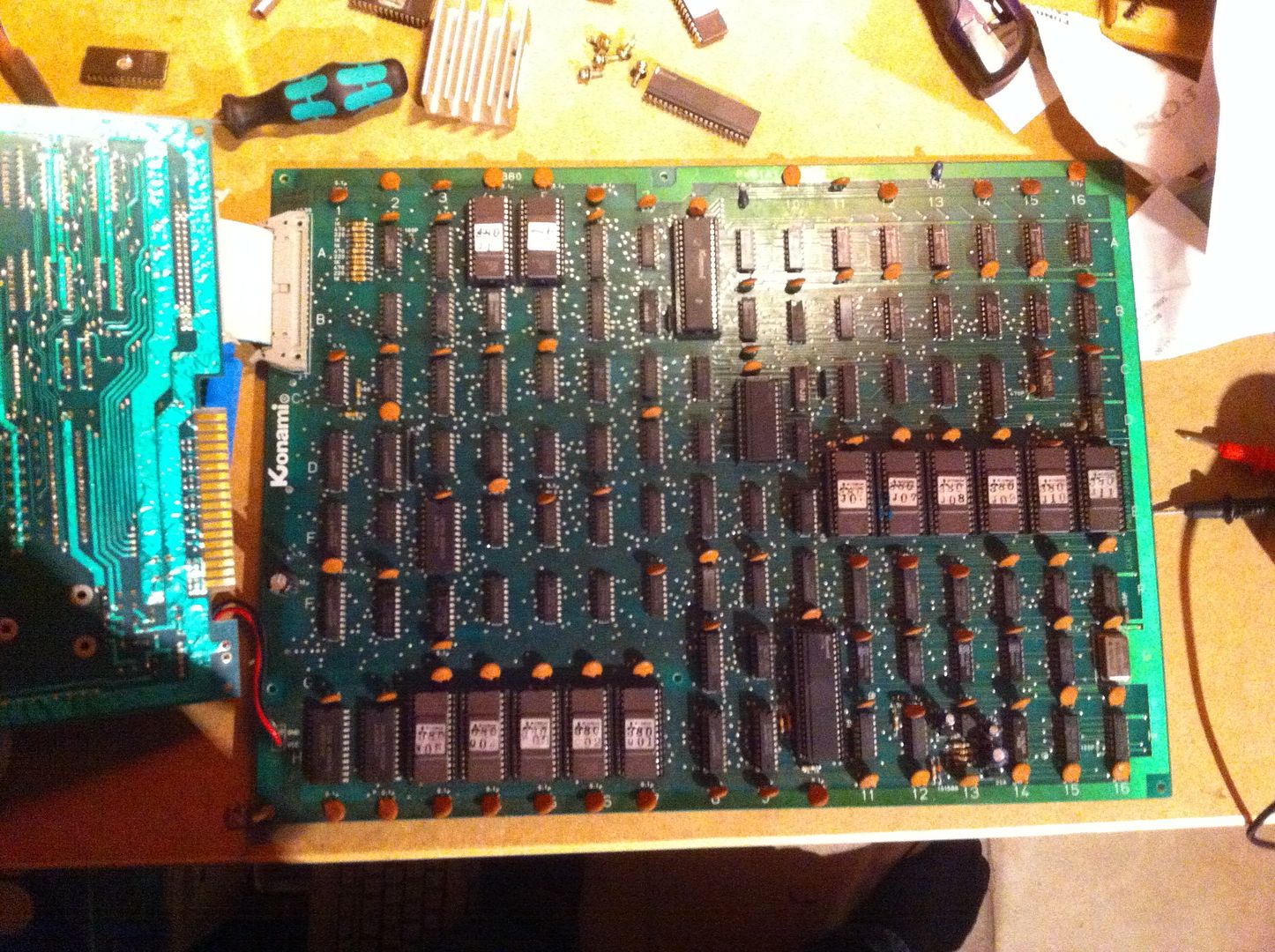
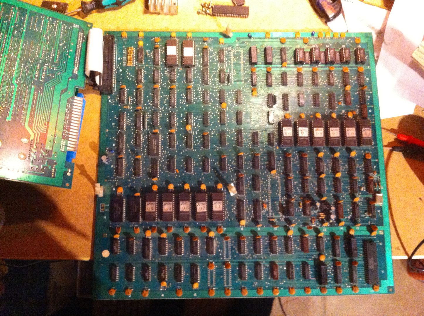
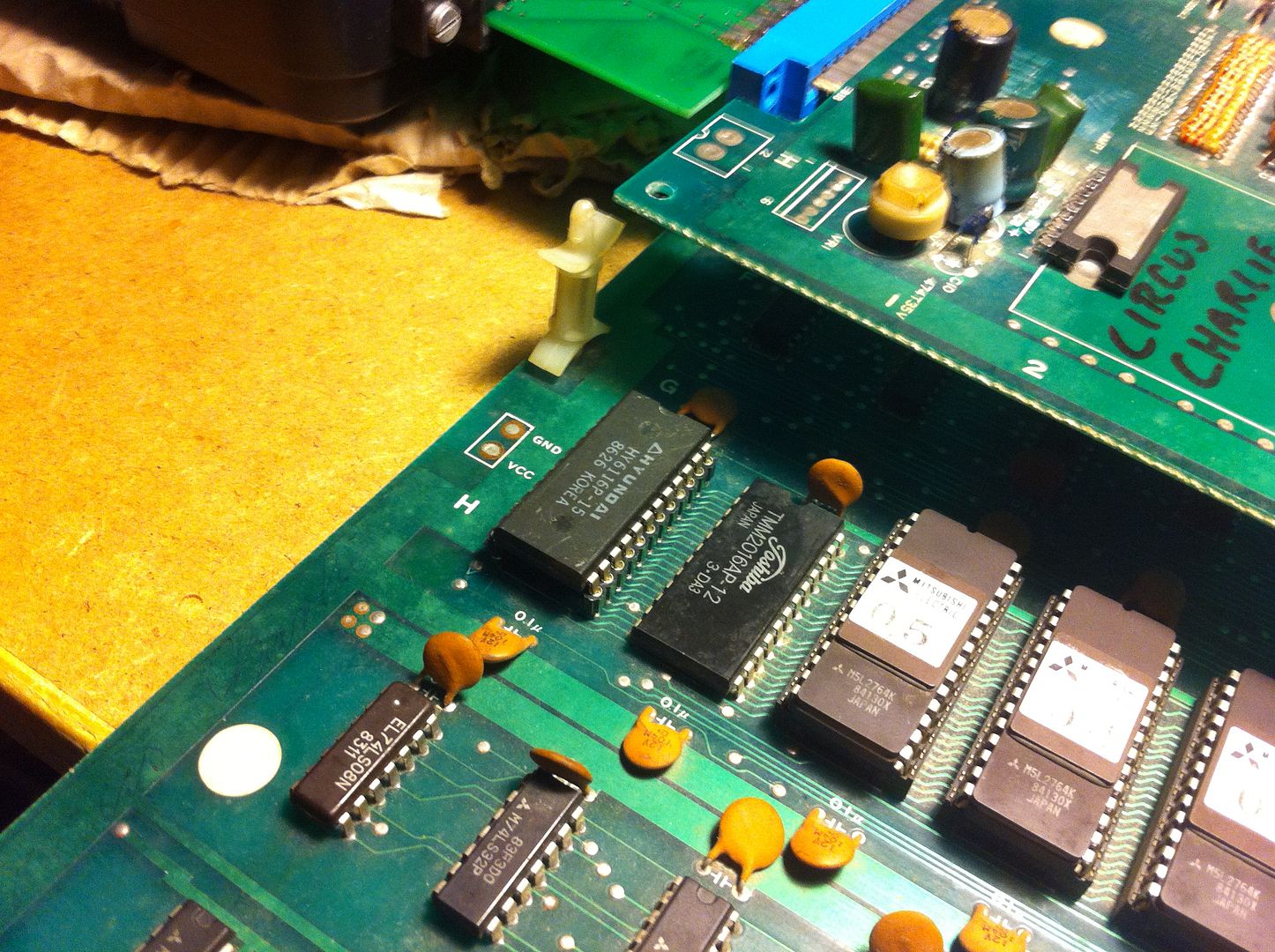
As part of the bigger deal, dorkvonwaterfall also gave me a defective bootleg of the same game for free, so I decided to have a closer look at that PCB; it might be in better condition than the original and might give me some pointers.

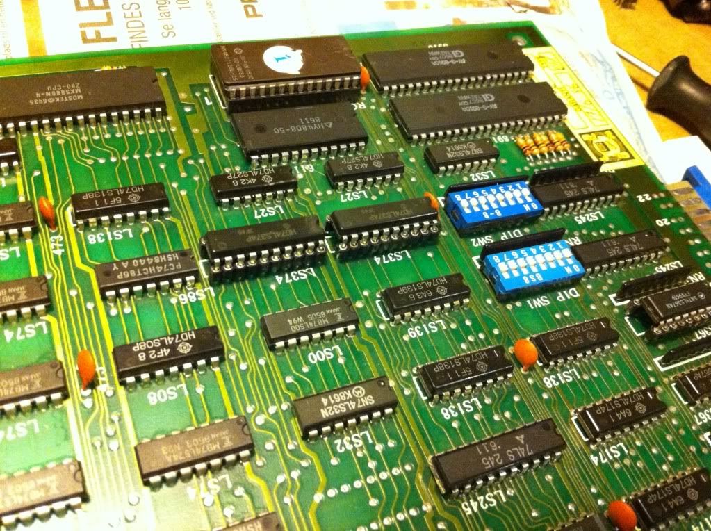
The boards actually look very similar


(original on the left; bootleg on the right)

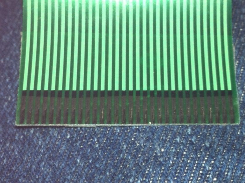
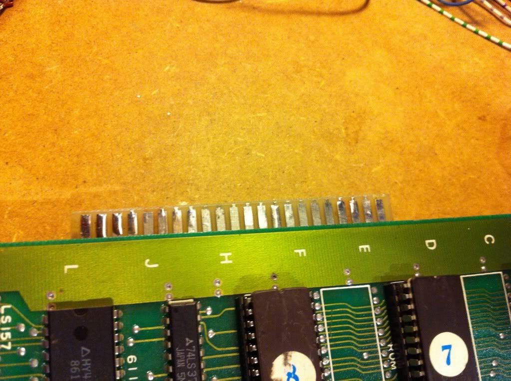
The bootleg is missing the custom ICs but has an extra strip of PCB at the bottom containing circuitry to make up for that. Here's a close up of the right side of the strip containing the standard Motorola6809.


Besides that, the two boards are almost identical.
After having done a quick visual inspection and dumped all the ROMs and checked them against MAME (they were all good), I discovered that the ROM set is identical to one of the original sets. That actually means, that the bootleg board is able to unscramble the opcodes on-the-fly at runtime, instead of, as I initially thought, using a ROM set with unscrambled opcodes.
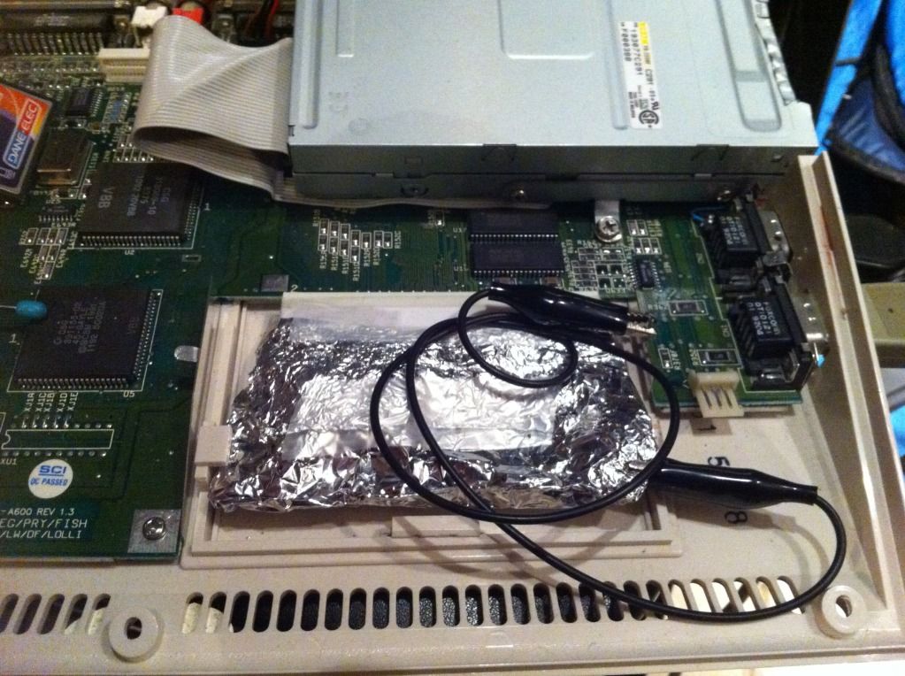
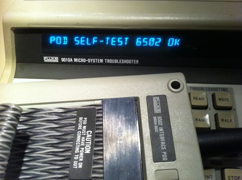
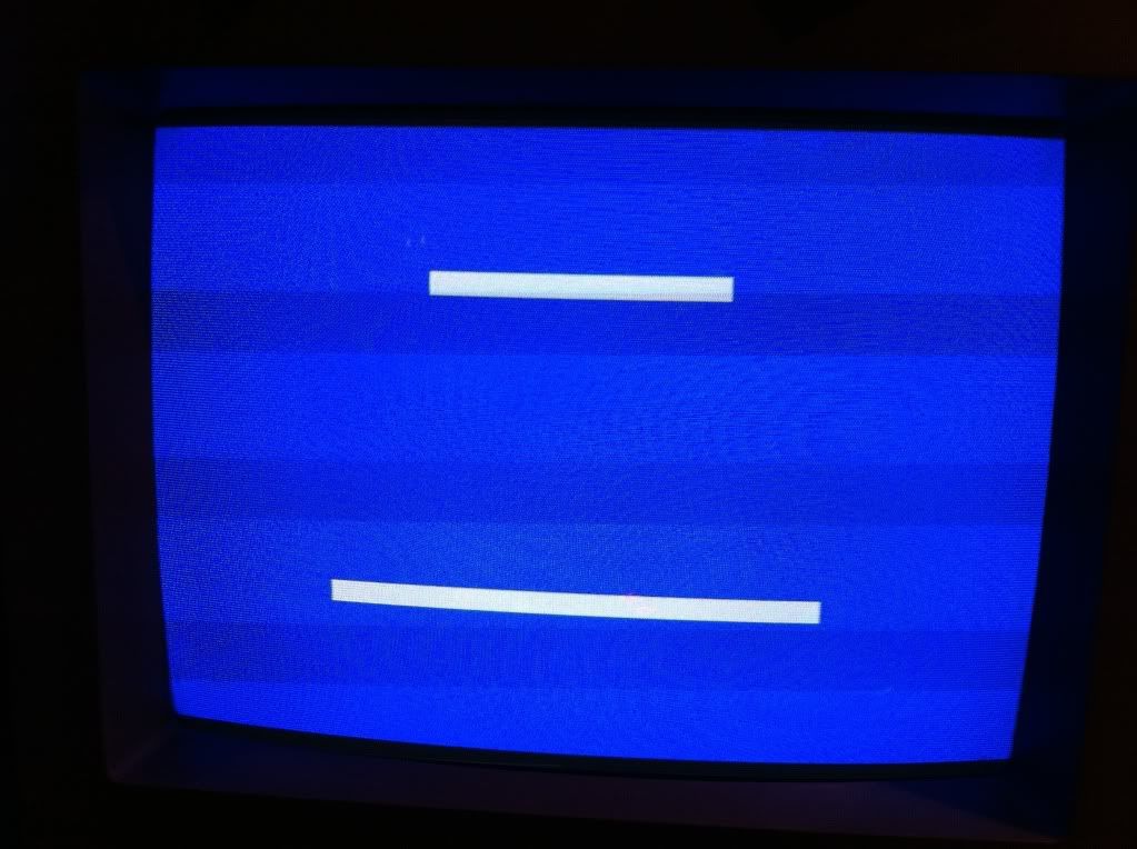
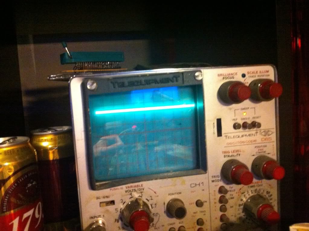
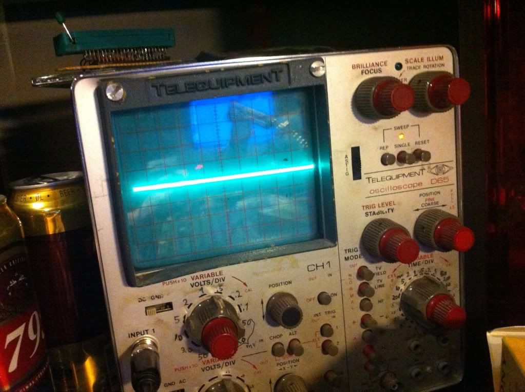
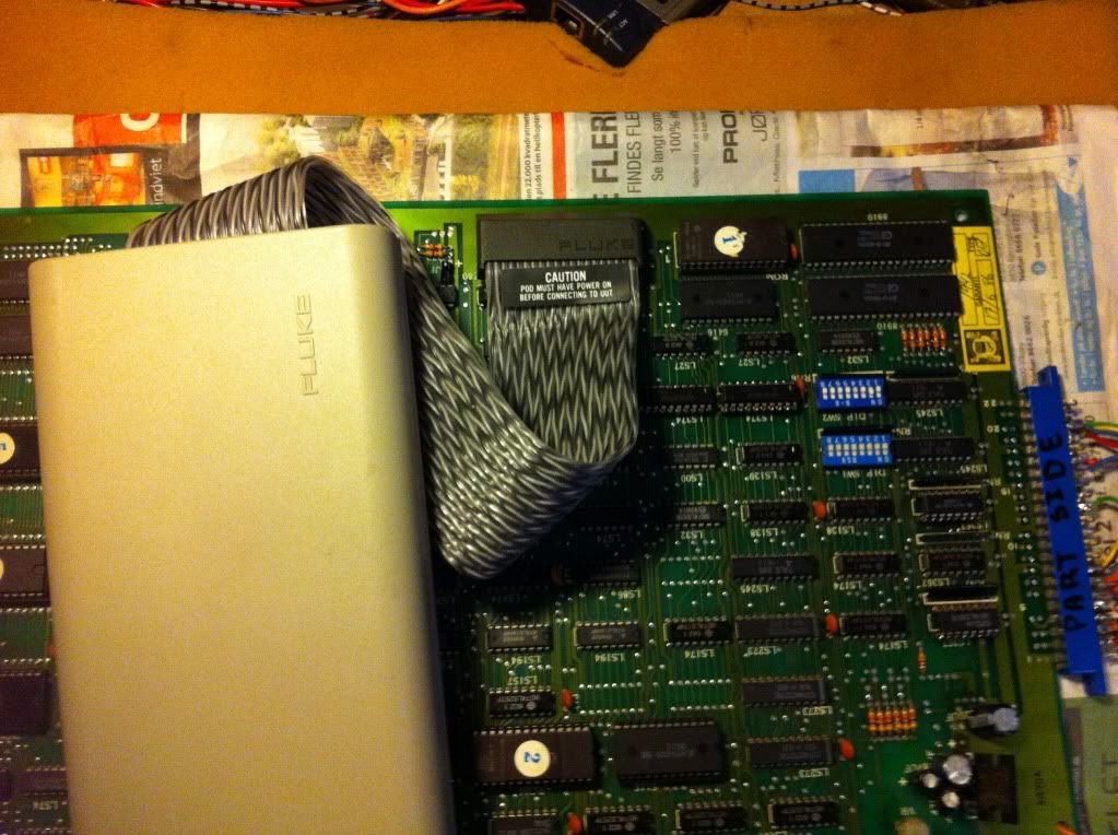
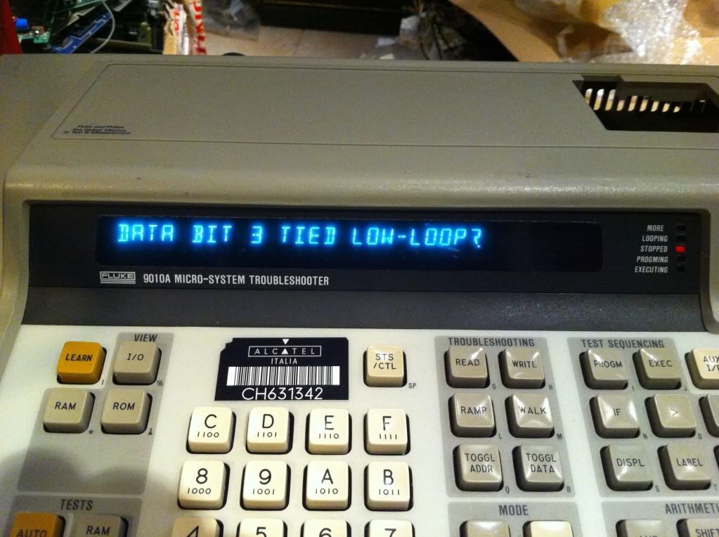
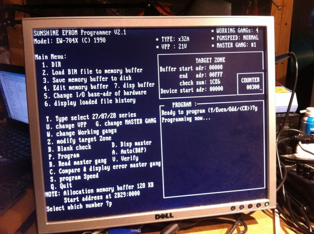
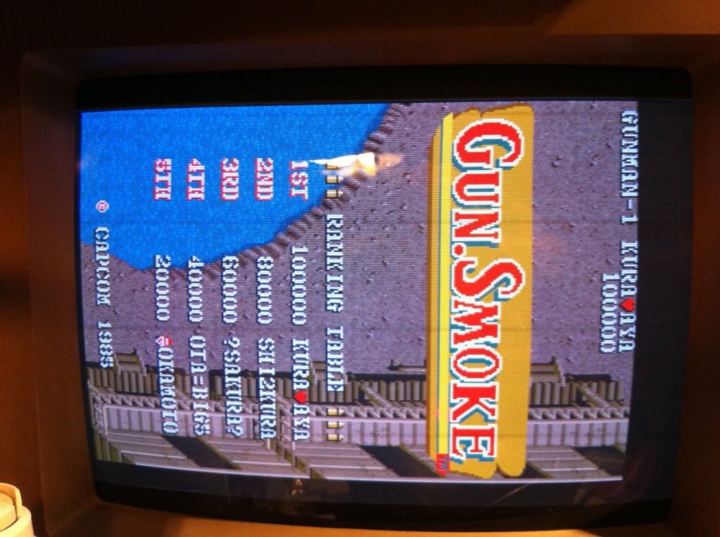
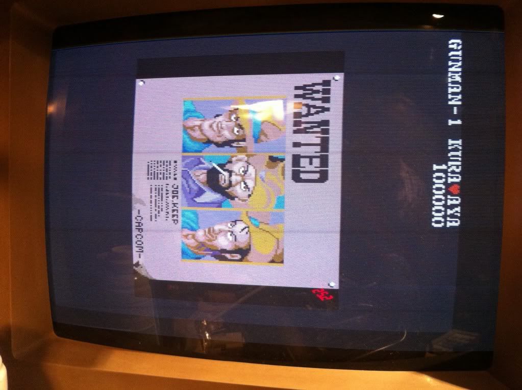
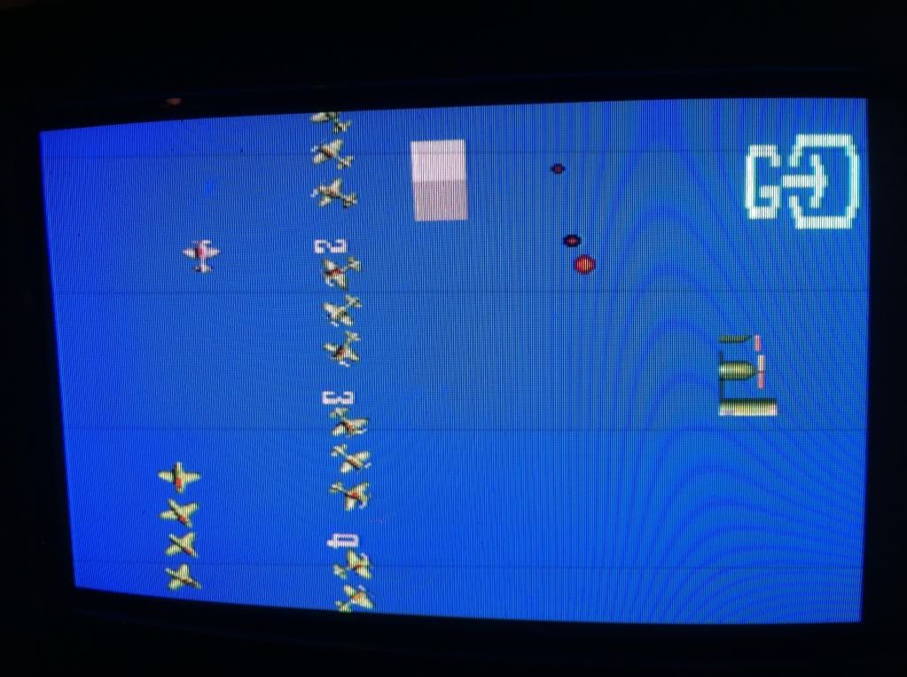
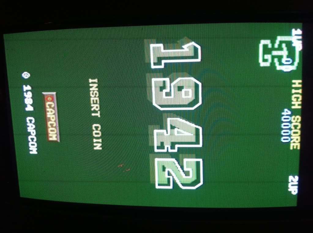
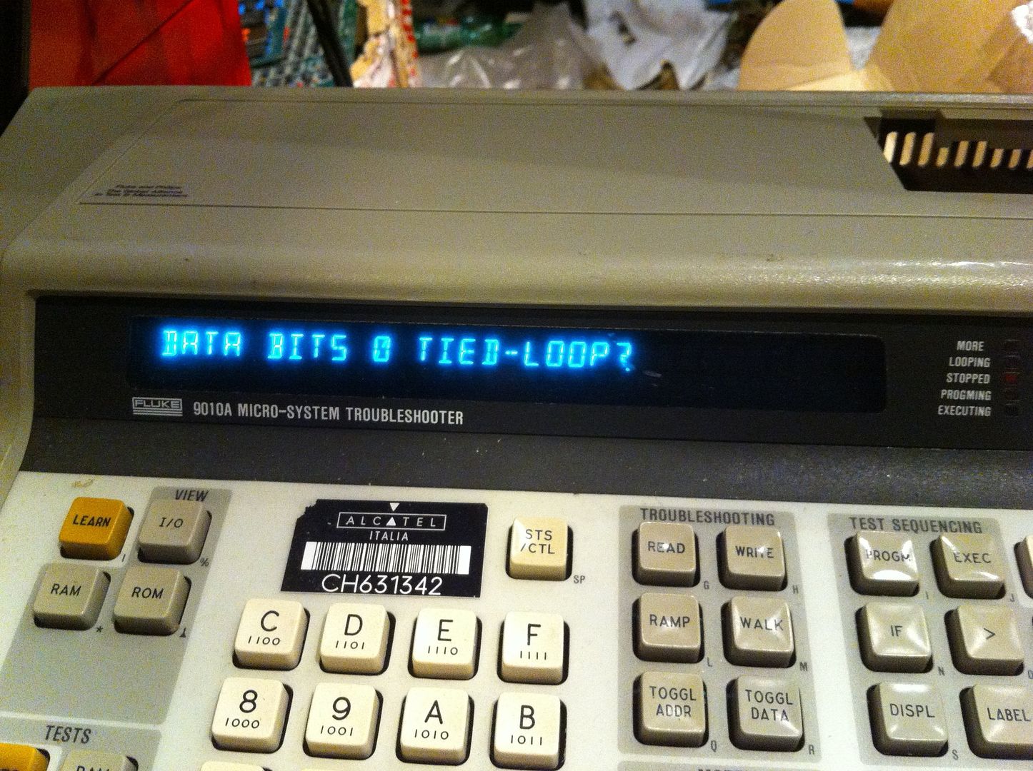
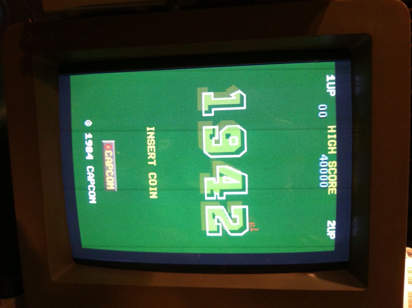
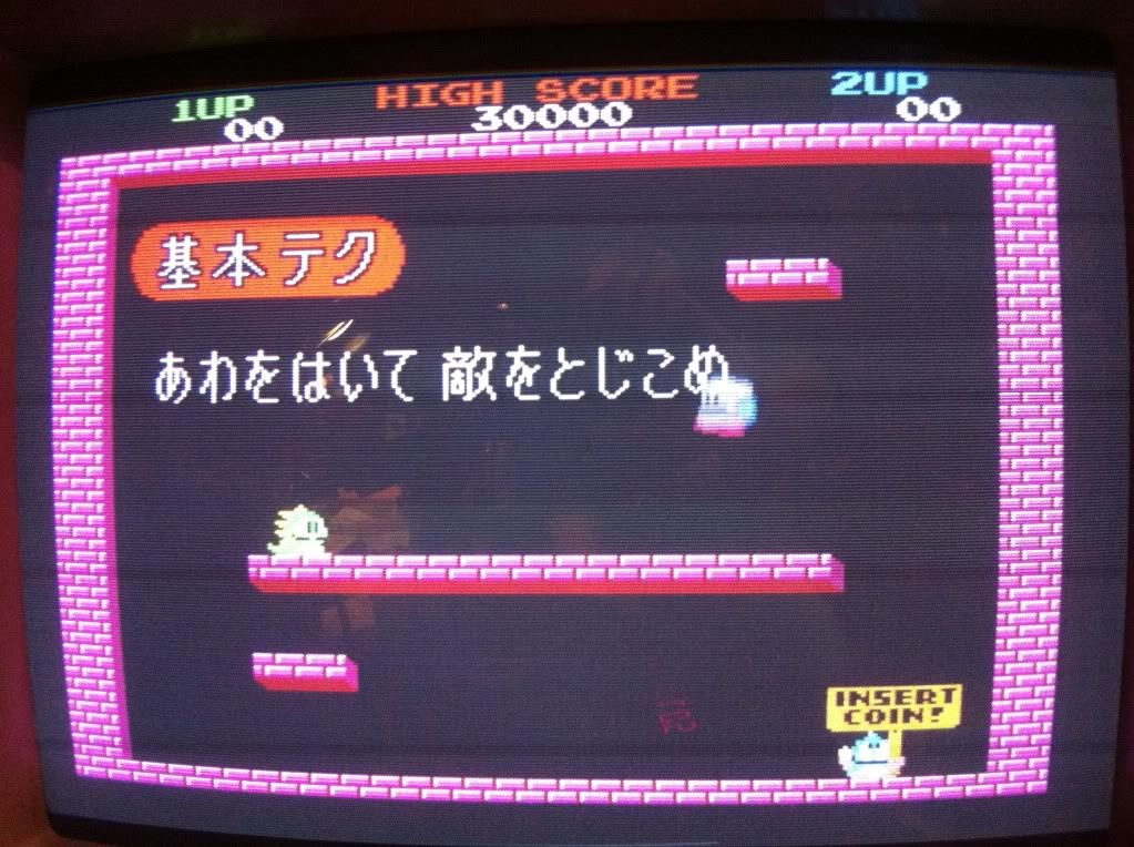
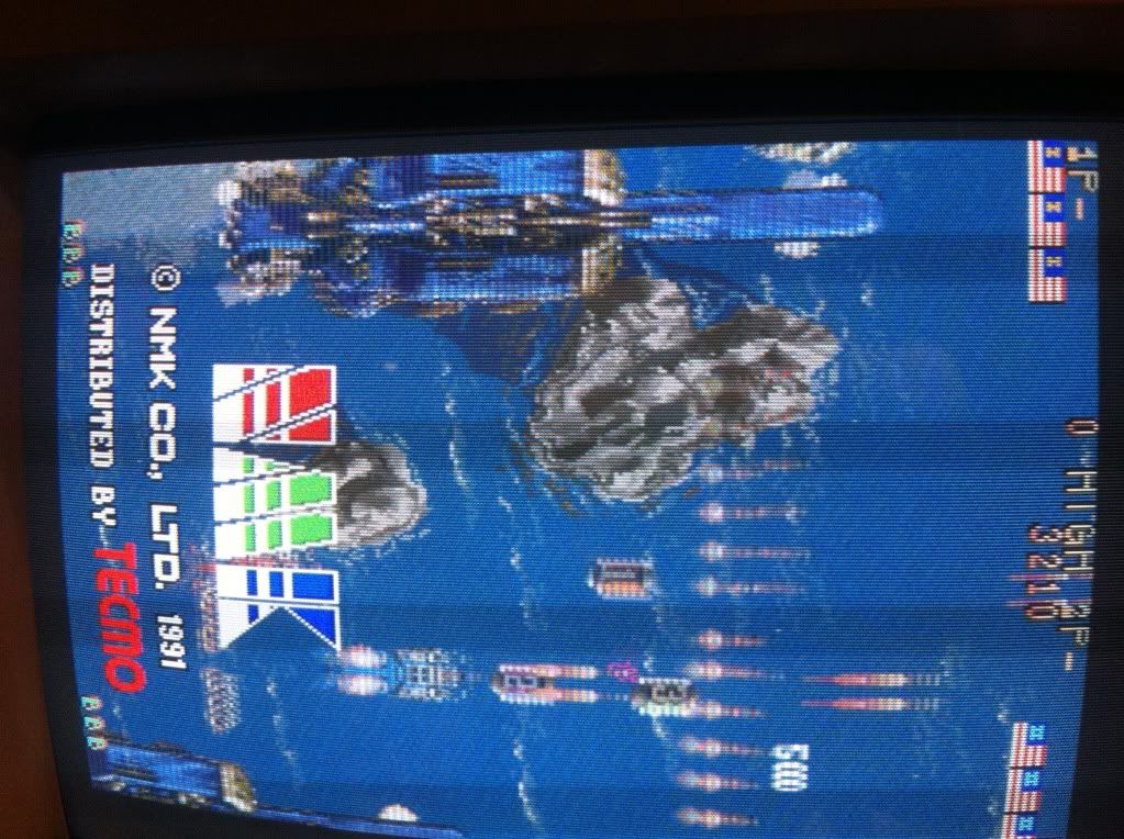
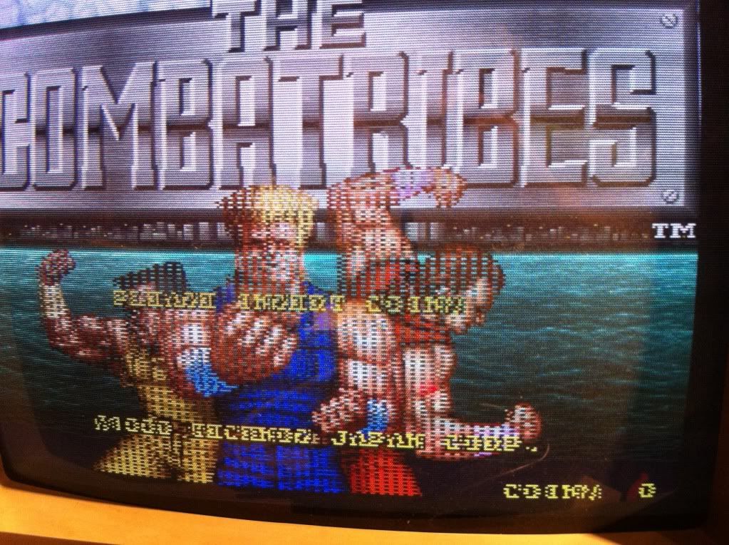
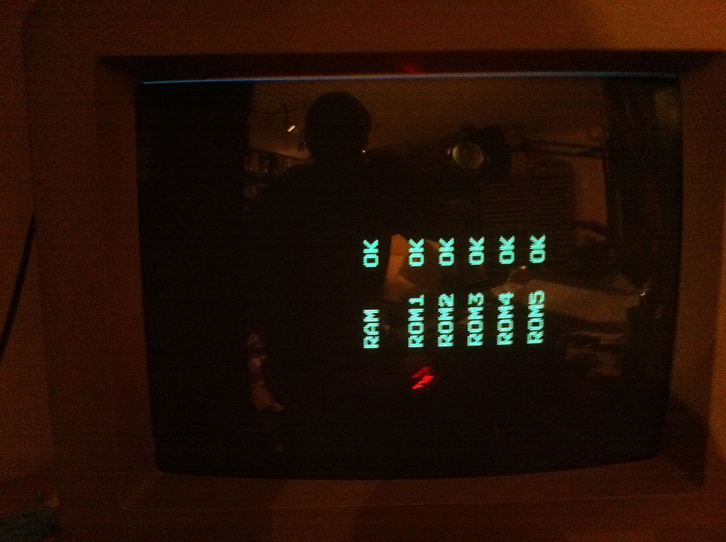
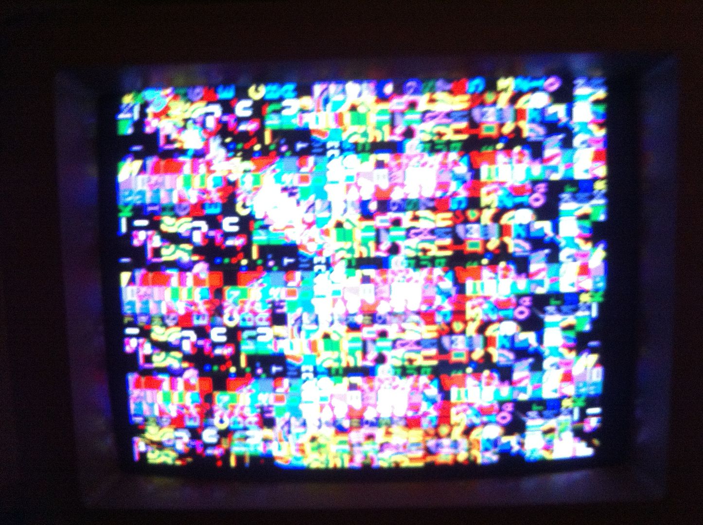
I hooked the bootleg up to my test rig and got a flashing screen, then this


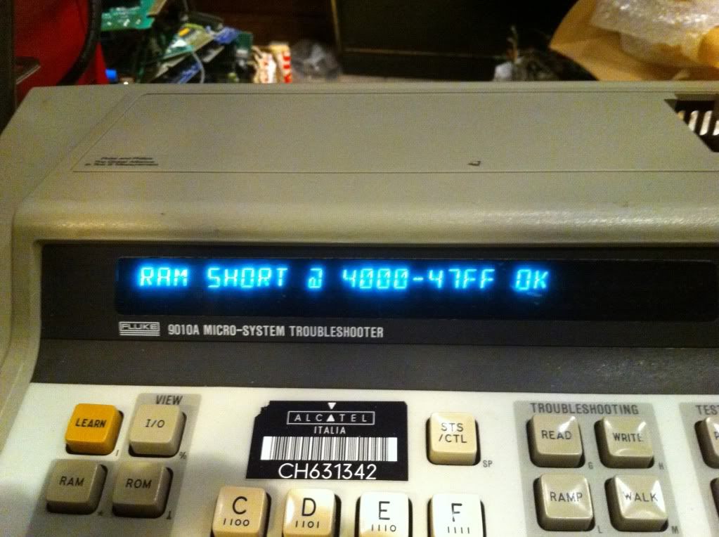
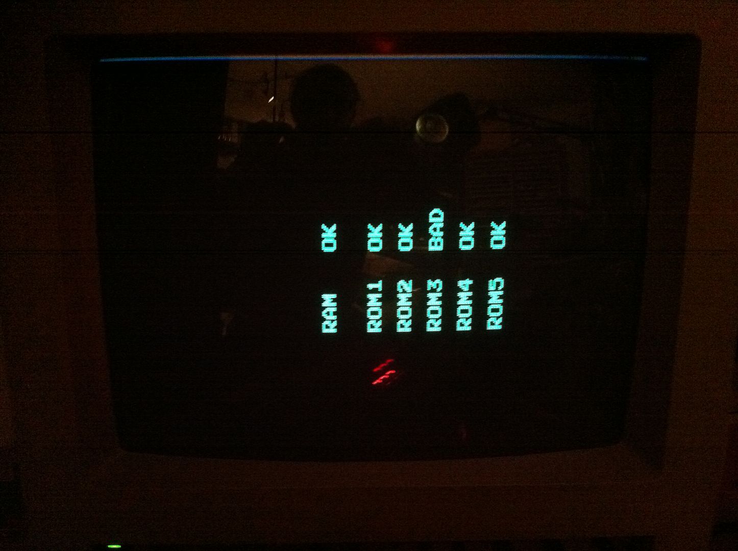
for about half a second. Then reset and the same over again...the watch dog was barking here as well. Even though the self test clearly indicated, that all program ROMs and RAM was ok, I had a hunch, that it might be a problem with one of the 2 scratch-RAMs. When peeking with the scope everything looked fine... hmmm. I tried piggy-backing a known good on one of the RAMs


and BAM!


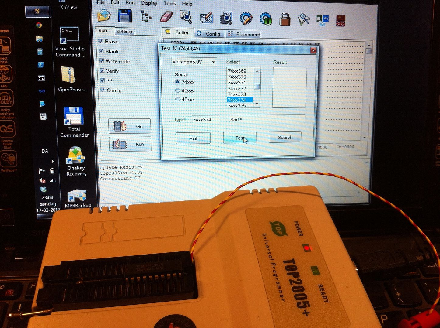
the game started up };-P I desoldered the RAM and tested it in the TOP2005+, but it came out good. I then fitted a socket and smacked the original RAM into it; watch dogging again. The game ran flawlessly with the other RAM IC; even the sound was perfect...


Without being 100% certain, I'm pretty sure, that the original RAM might have a timing issue, and that's why it passes the off board test in the TOP (and boards self-test), but doesn't actually work correctly runtime. I now had a fully working board (almost) identical to the original I was to repair. This is usually the best situation you can have when doing a repair, ever };-P

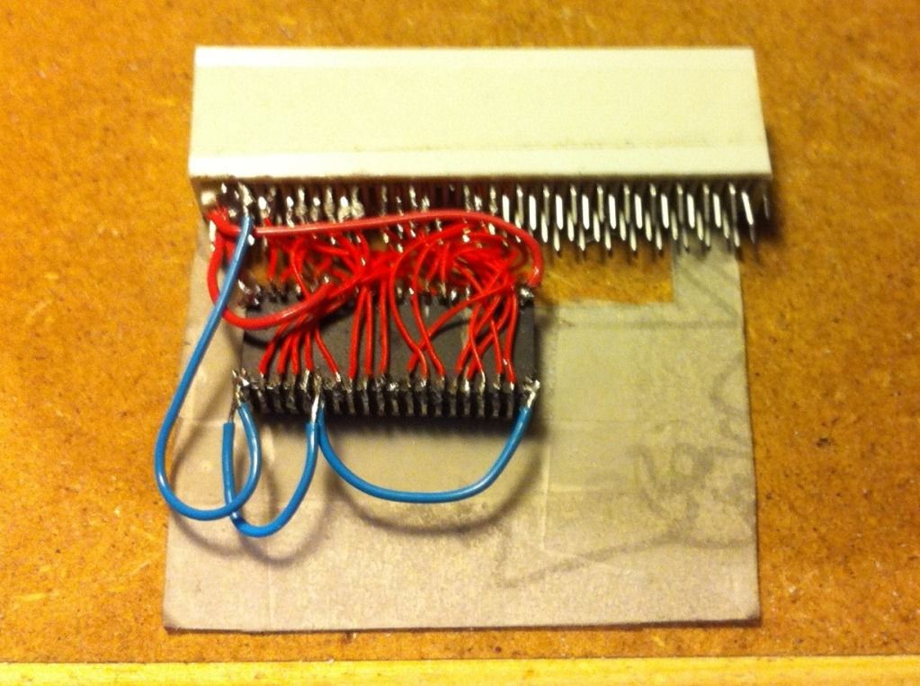
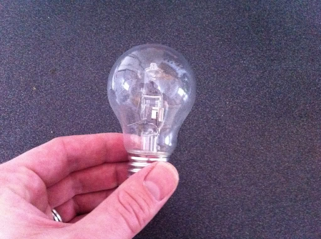
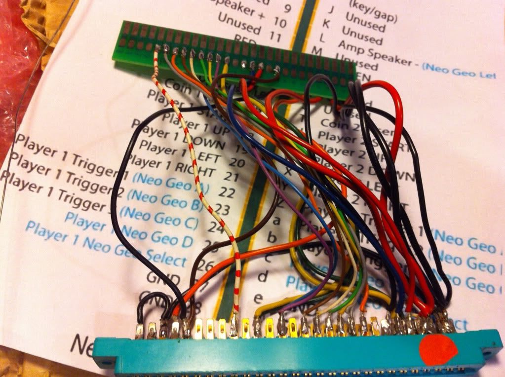
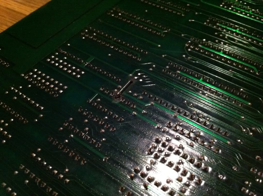
Now on the bootleg all the wires from the Konami-1 mash-up on the extra PCB-strip is still connected to the original points where the CPU sits on the original. So it was pretty simple to compare measurements between the two. And as I suspected, pin 42 on the bootleg was very active at all times. So either the Konami-1 CPU was toasted, or something downstream was pulling the line down. So following the schematics, I tried removing the only IC that connected directly to pin 42 (a 74244), but the line remained stone dead }:-S. I did, however, have one small hope left: On some rare occations, a pin can snap just inside the IC casing. So with a little luck you're able to carve a bit of the casing away, and solder a wire on to a piece of lead that still connects to the actual sillicon circuit inside. So I placed the CPU in a socket on a board from the scrap pile and started carving using a file.


But alas! After having reached the metal, there was no visual signs of breaks


and when peeking with the scope, the line was still stone-dead. So basicly to fix his game, I would have to somehow get hold a replacement for the dead Konami-1 custom CPU.
So I send out cries for help on the different arcade forums I usually visit, and got an answer };-P The user Soren (Søren) from spille-maskiner.dk (and now friend of mine through chassisarcade.dk; he more or less keeps their pinballs up'n'running and also, like me, hang out there wednesday nights) wrote to me, that he had an original defective Hyper Sports, that he would kindly let me borrow; jawsome! Luckily this board also had the Konami-1 socketed, so I didn't even have to do any desoldering.


I slammed the CPU into the original Circus Charlie and now had an active pin 42 };-P However, the game was still watch dogging, was dead silent and had a black screen; but at least it was some progress...
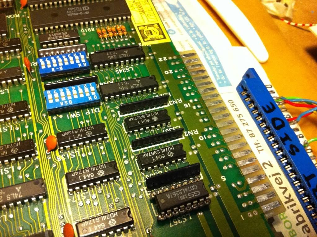
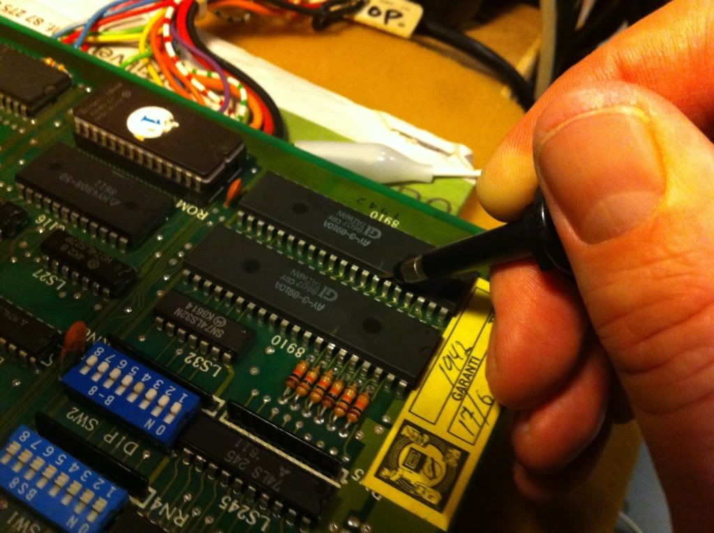
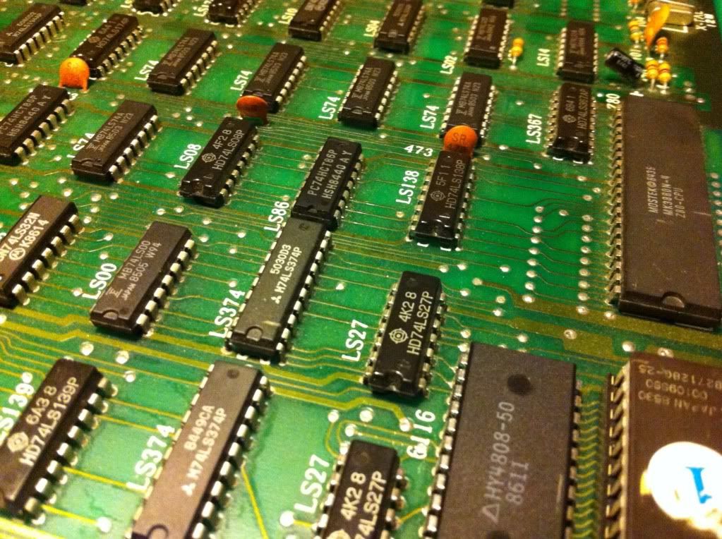
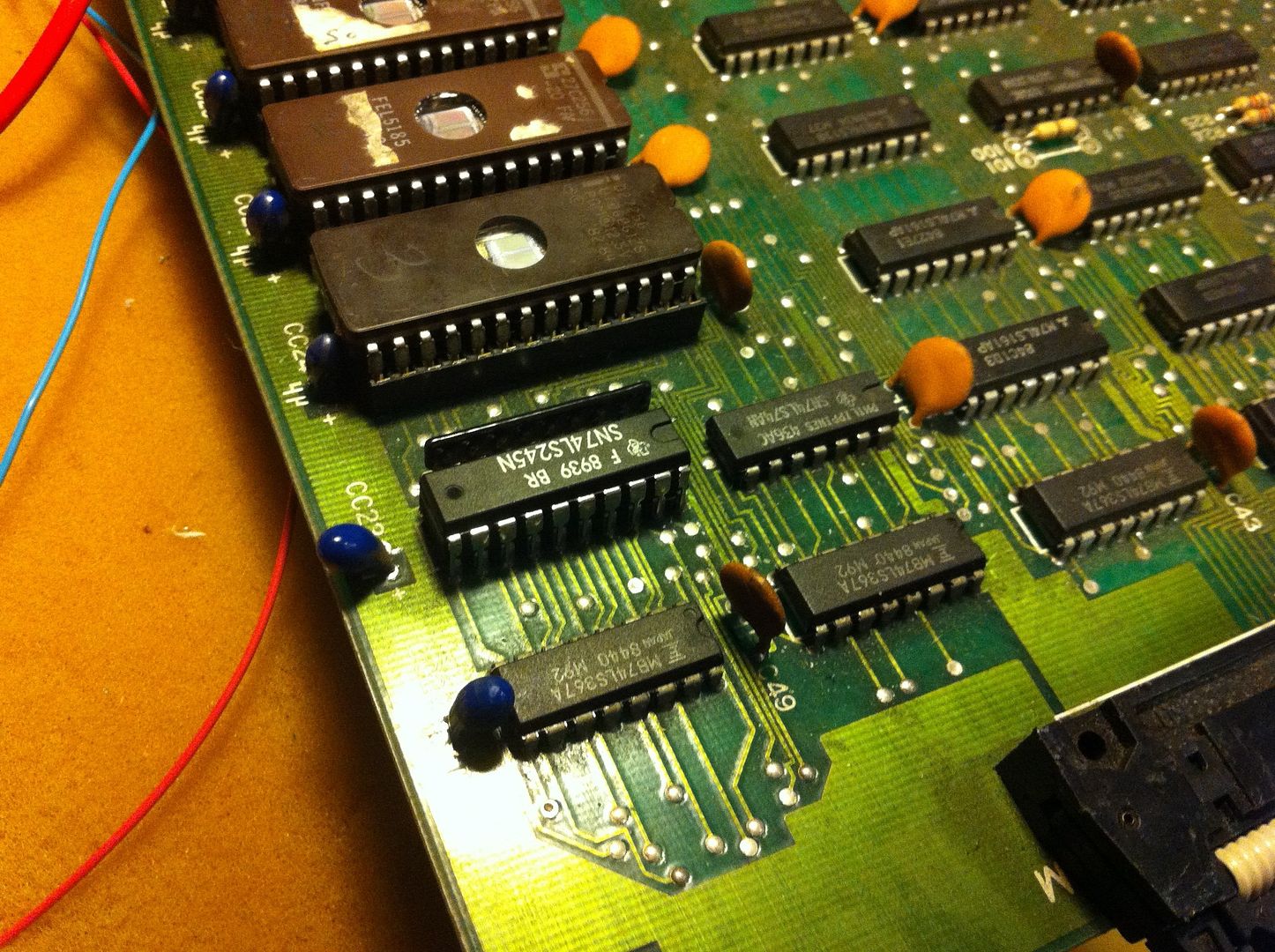
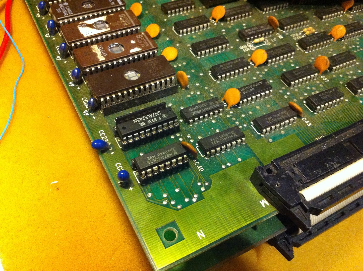
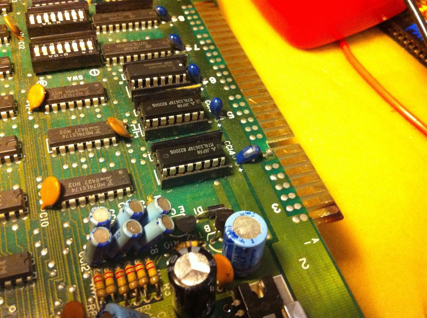
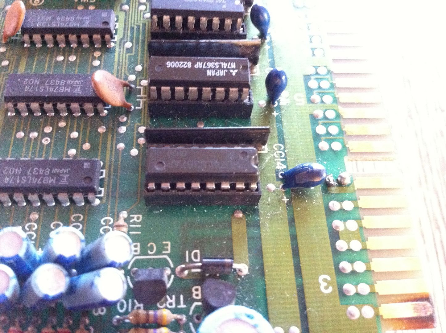
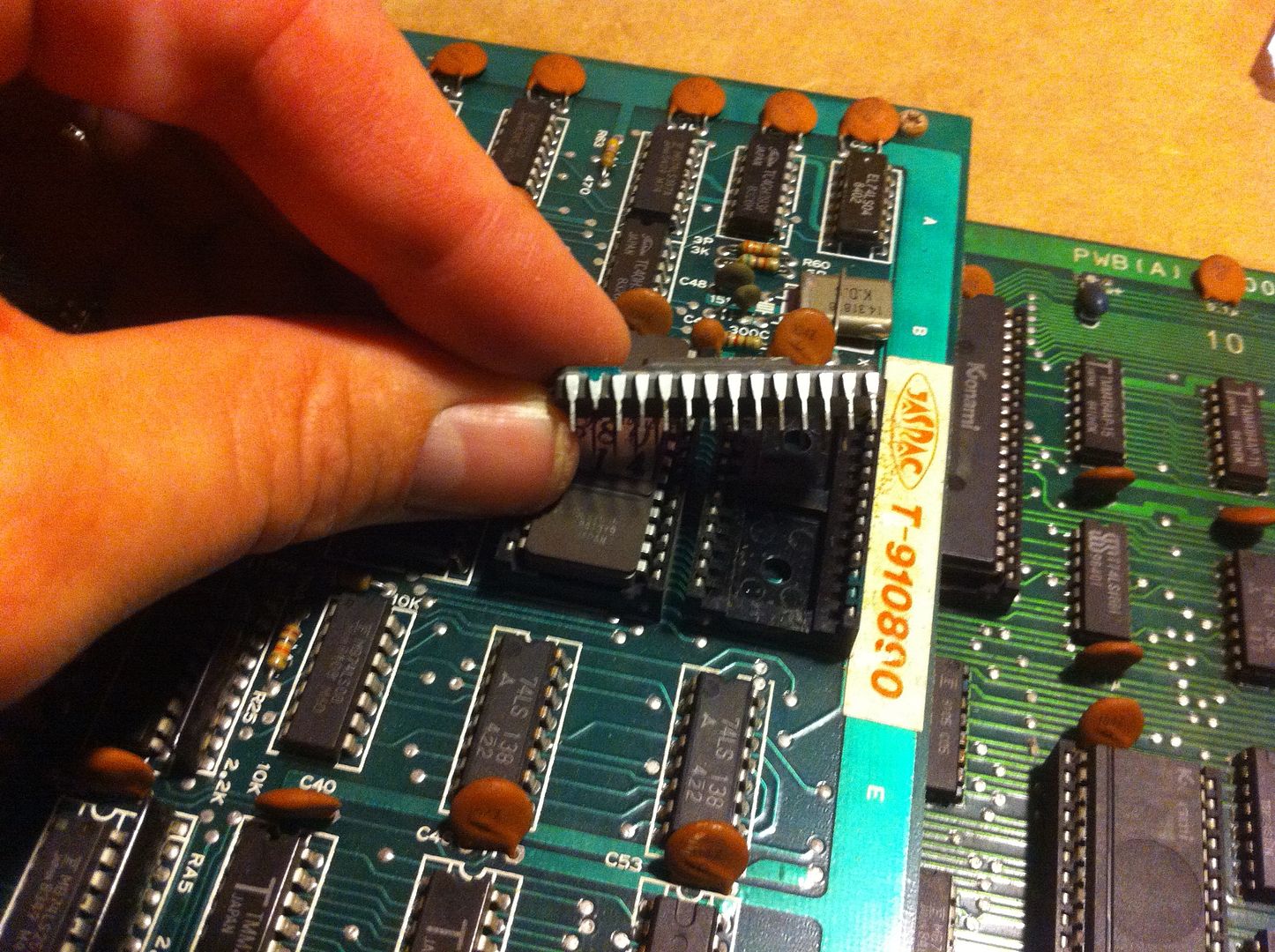
Now as the game suffered from a lot of corrosion on the socketed ICs, these were my first suspects. So I started checking each of them with the continuity tester by measuring between the IC pins and the pins of the socket on the solderside of the PCB. Starting with this custom IC in the final stage of the graphics section


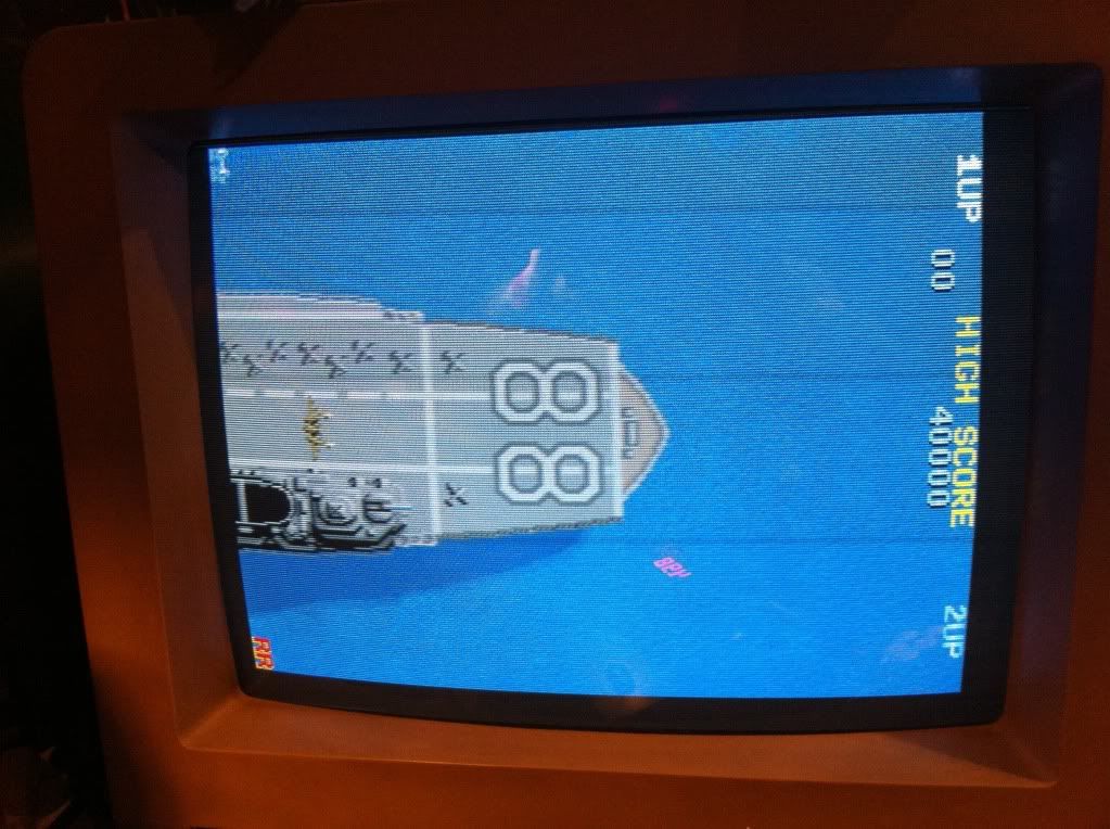
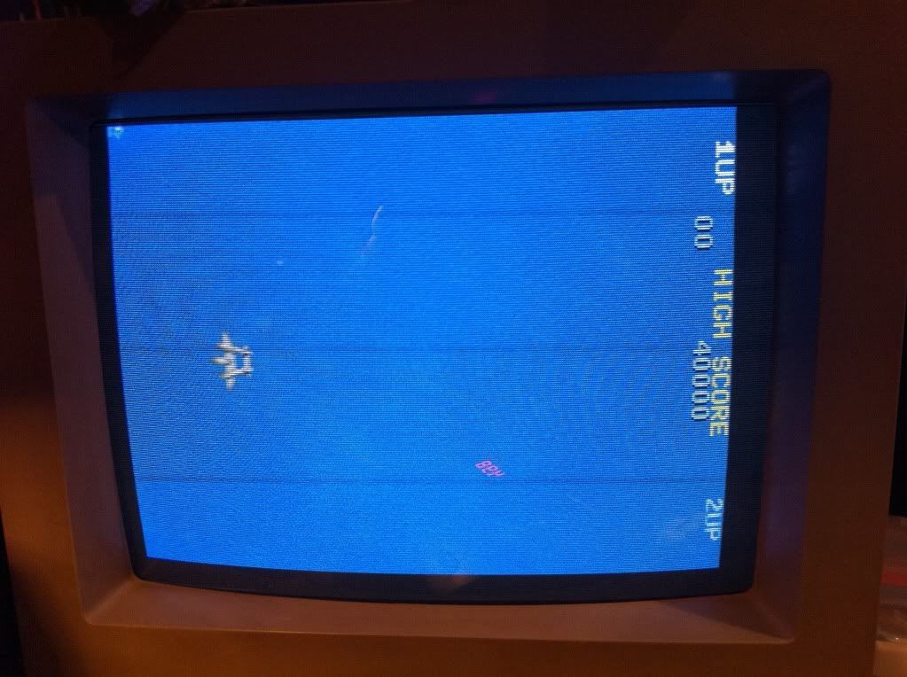
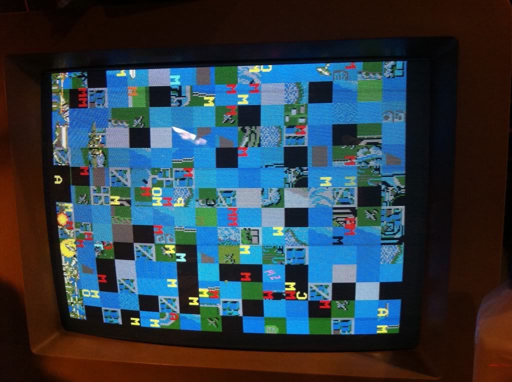
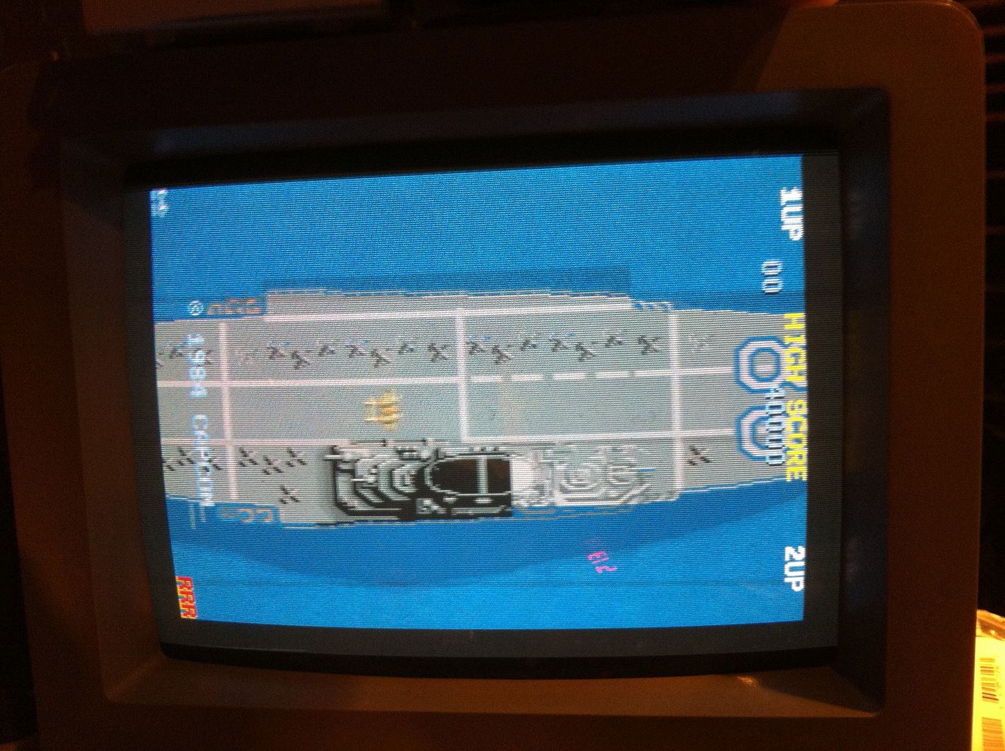
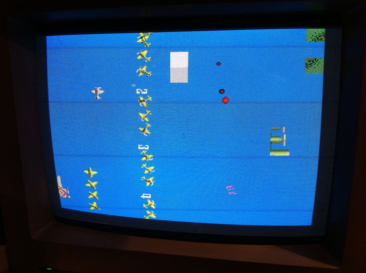
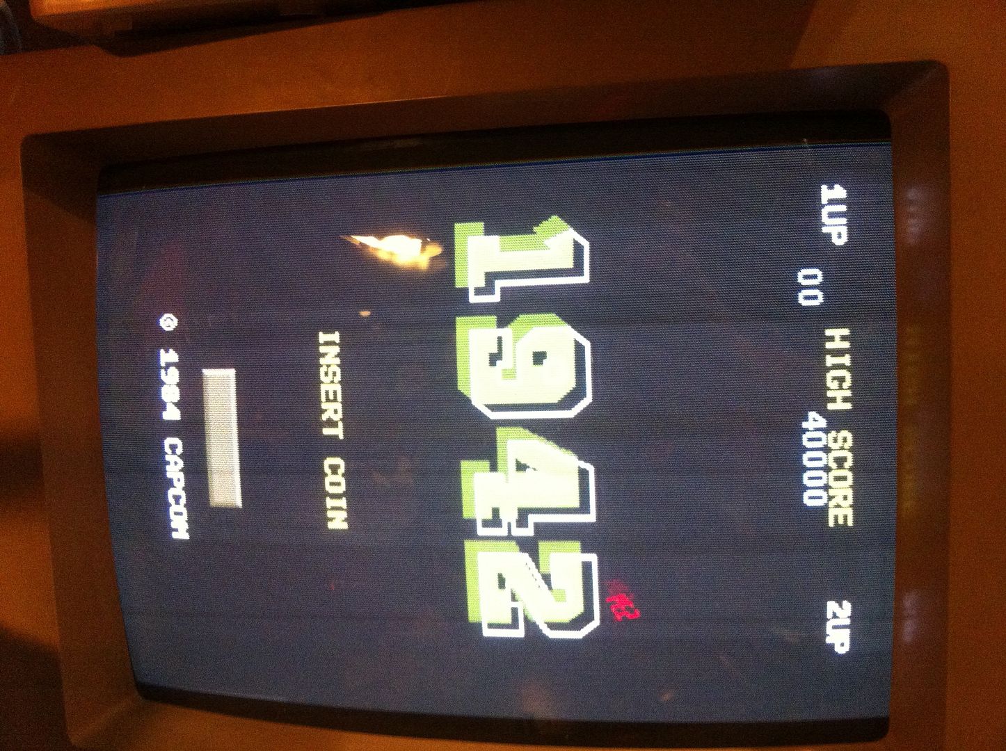
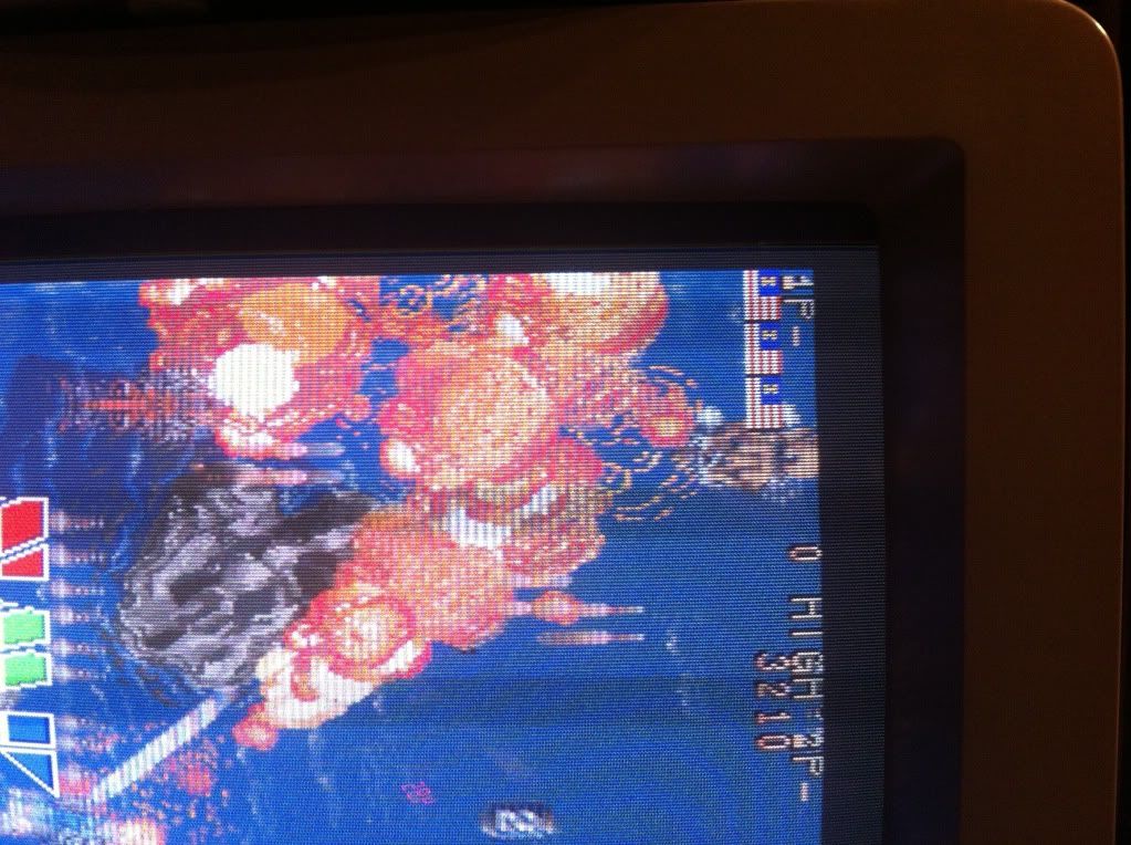
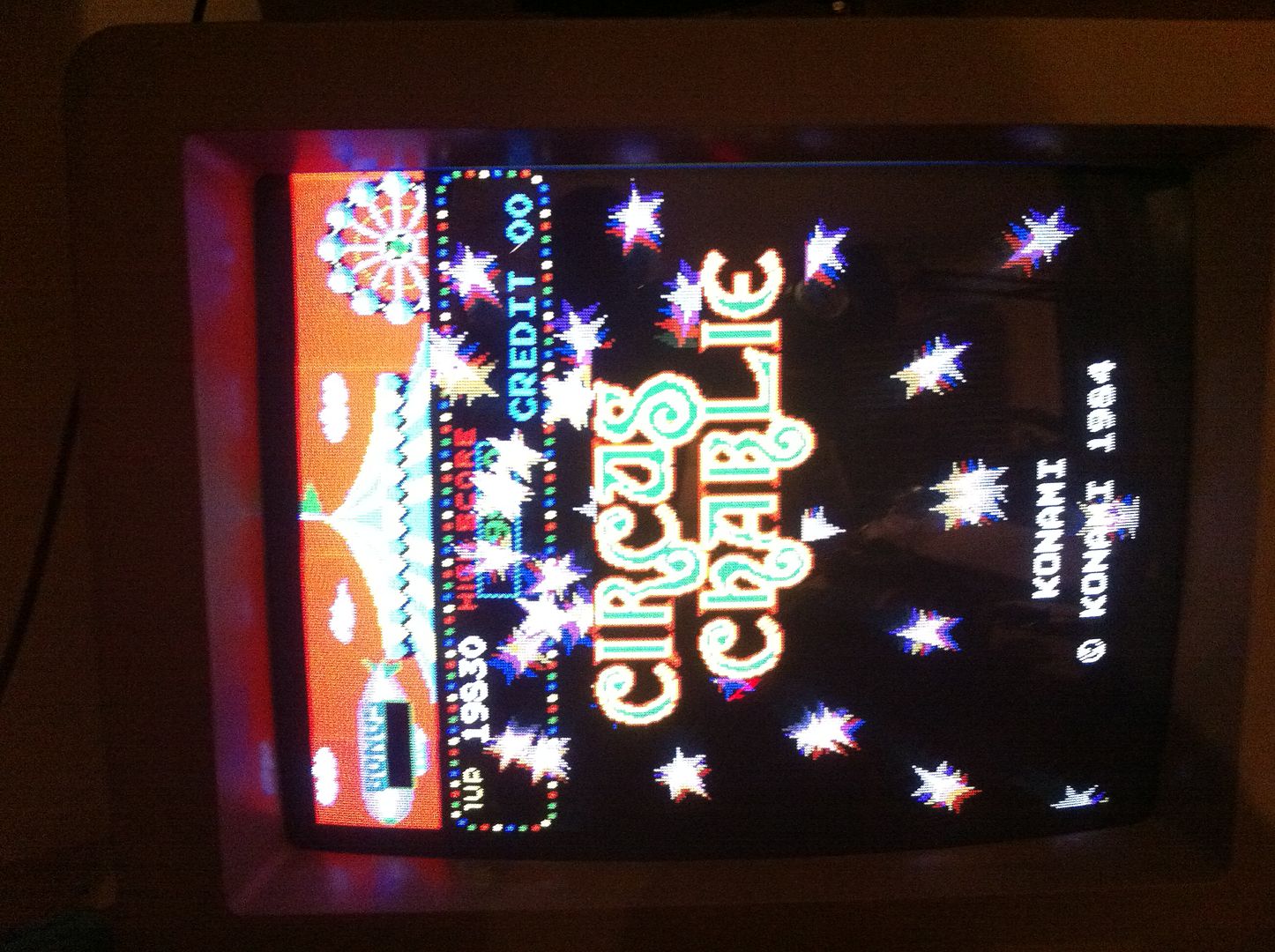
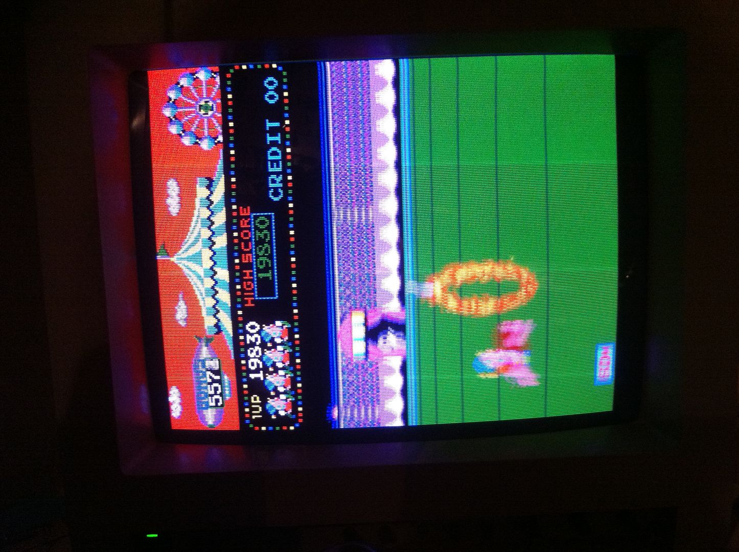
I found 3 pins unconnected. After giving both IC and socket another treatment with Stanley knife and steel wool (I REALLY want a fiber glass brush for X-mas this year), all the pins made connection again. I connected power, and now got a screen flipping between the following two images:


ROM3 also had 2 pins not making proper connection and was given the same treatment as the custom IC. Aaaaaand....


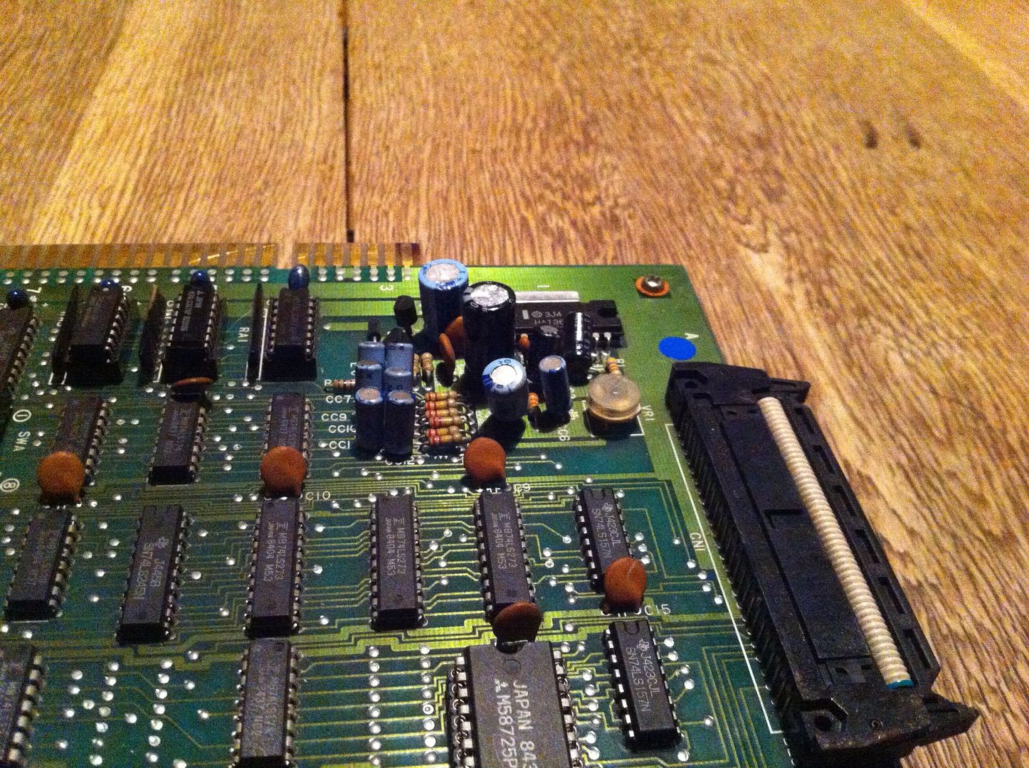
OOOOH JOOOOY! };-P Everything worked perfectly, except for the sound, of cause; as I'd removed the AMP and the volume pot. The AMP is an LA4461, and I only had some new LA4460 (the mirrored version) stocked. But as it's fitted with a heat sink on the PCB, the mirrored version wouldn't fit properly. The bootleg, however, didn't have a heat sink, so snatched the one from there, and fitted the bootleg with the LA4460 };-P
And lo and behold; after fitting the volume pot again as well, it brought back the sound!

The only thing keeping me from closing this case now, was to find a working Konami-1. I actually started a project of trying to reverse engineer the bootleg mash-up and make a daugther board, that could be used as a replacement, but found it too time consuming for now. So after some time, I stumbled upon a cheap defective 
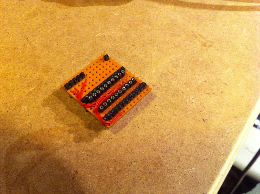
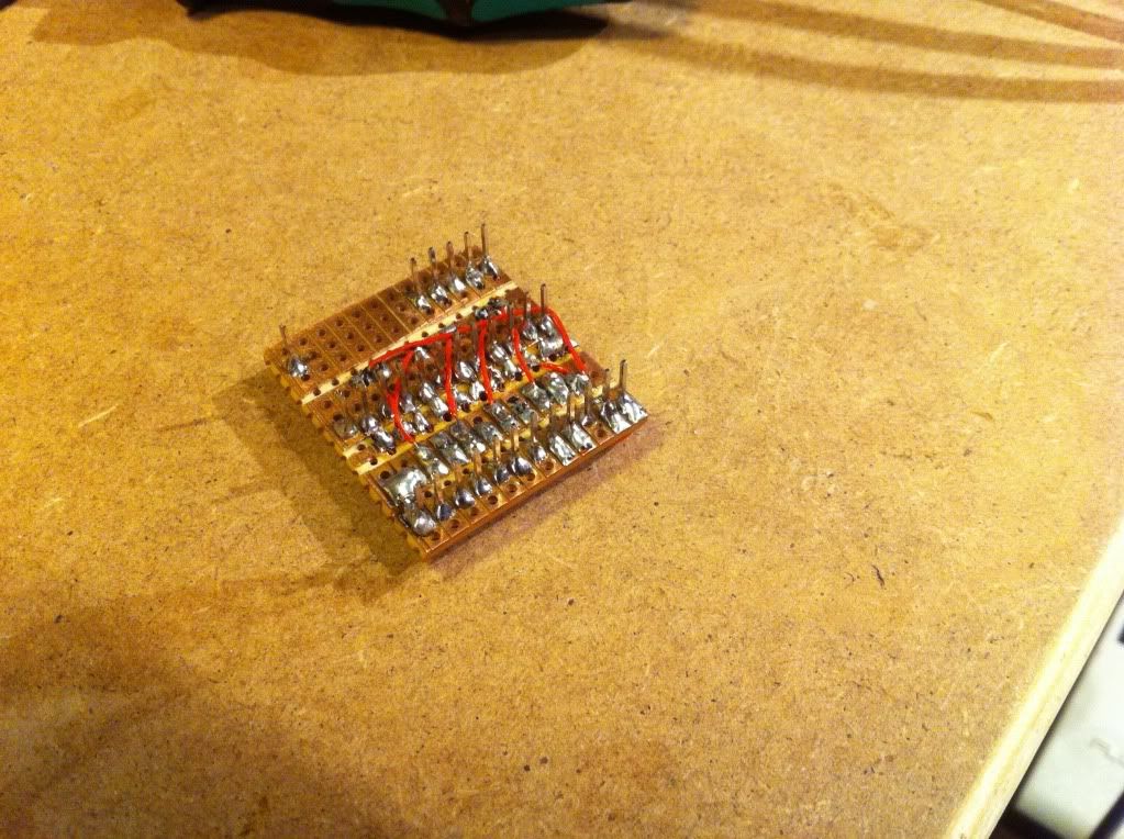
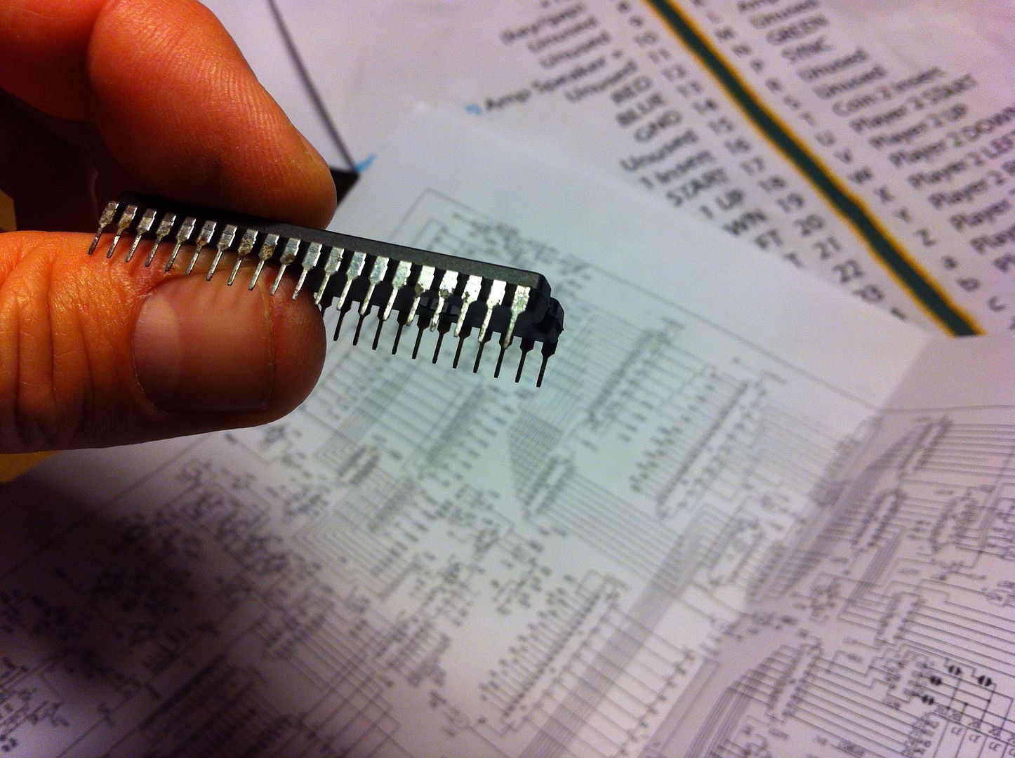
Roc'n Rope on evilBay and decided to buy it. When I inserted this CPU, the game started to watch dog again... had I bought a defective CPU? }:-S But I discovered, that the CPU socket was actually in pretty bad shape, due to the corrosion, so I replaced it with machined pin header strips.


And finally the game was in perfect condition and ready to be returned to it's rightful owner };-P

So now that the board is getting send back, is Elgen giving up on the Konami-1 mash-up, as he will not be able to test it, you might think? Weeeell, not quite. Because I actually discovered, that if I fitted a socket on the bootleg where the Konami-1 was suppose to sit, and removed the 6809 as well as 2 socketed PALs, I could insert a Konami-1, and the game would run quite happily.


So I just might pick up this exciting task again, some time in the future };-P

Konami Circus Charlie (revisited)

$
0
0
Not long before Christmas last year, I finished repairing an original Konami Circus Charlie for member dorkvonwaterfall on spille-maskiner.dk. Before carefully packing it, I tested and flexed the board several time to make sure it was durable enough to withstand being transported by The Danish Postal Service. However, after poor Dirk received and tested the board, he sent me this sad video:


Apparently, the board had developed a sprite error during transport. We arranged for me to have a look at it again, and a few weeks after New Year, I had the board back on my test bench again. I was pretty sure of what was wrong: The crappy sockets that Konami had used for the ROMs. And checking with the continuity tester confirmed my hunch. So I desoldered all the 6 sockets for the graphics ROMs


and replaced them with (as I always use) machined pin breakable header strips


And now, the sprite error is gone


After having tested the game several times and flexed the board, I'm now hoping that it'll reach it's rightful owner (again) with no additional errors.
Viewing all 33 articles
Browse latest View live